In this tutorial, we are going to create a gamecontroller which can control the game using movements. By tilting the gamecontroller, you can control the movement of the basket. We will extend the game made in the previous tutorial.

Carrying out the assignment
Realizing the gamecontroller can be done in 2 ways:
- Using the MPU-6050 Accelerometer & Gyroscope sensor.
- Streaming the Accelerometer & Gyroscope sensor data from your phone to the game.
These different options are discussed in step 1 and 2 of the assignment. You must choose one option, then do only that step. After that, continue with step 3 (realize communication with the gamecontroller into the game).
What do you need for this assignment?
- Arduino and Eclipse IDE
- An Arduino: it is advised to use the BLE-Nano, however, step 1 can be done with the regular Nano also.
- A display (preferably the OLED display)
- Documentation: Arduino tutorials and pinout schemes.
- Arduino libraries (most of you will have these already): U8g2 (for the display)
You can install a library via the library manager (Sketch > Include Library > Manage Libraries). Eg. by searching for its name in the library manager.
Tutorial steps
- Build controller with MPU-6050 Accelerometer & Gyroscope sensor
- Build controller with phone
- Realize communication with the gamecontroller in the game
- Add extras
1. Build controller with MPU-6050 Accelerometer & Gyroscope sensor
It is advised to use the BLE-Nano to build the controller. However, you can use the regular Nano also. A disadvantage is that it is more difficult to switch if later on you decide to use the alternative way to use the phone as the controller (step 2).
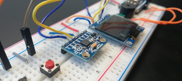
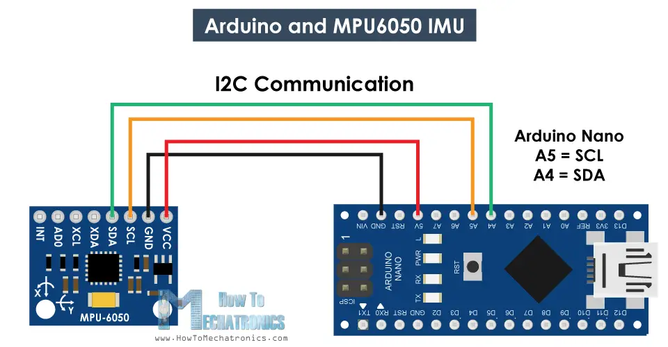
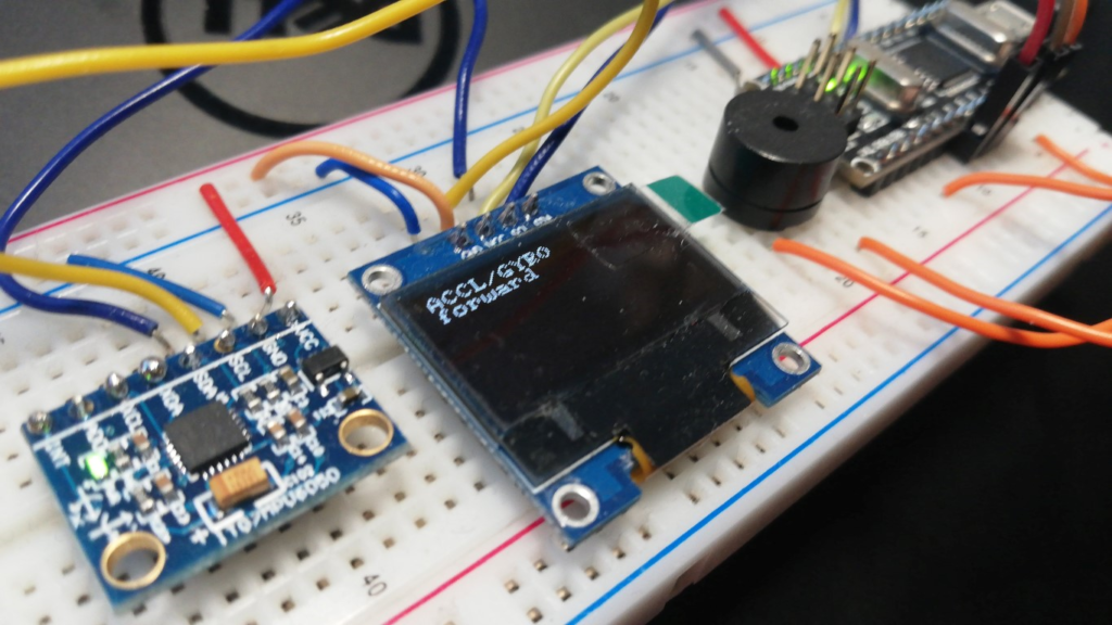
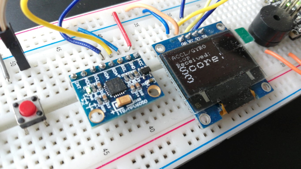
Connect both the display and the sensor to the I2C ports (A4/SDA & A5/SDL) of the Arduino. Connect GND and VCC (5V) of the Arduino to the blue and red tracks and connect the display and sensor to both. This has been done in previous tutorials too, like the distance sensor tutorial.
In the example photo above buttons and a buzzer have been added. They are not needed for this part of the assignment. For now, you only need the display and the sensor.
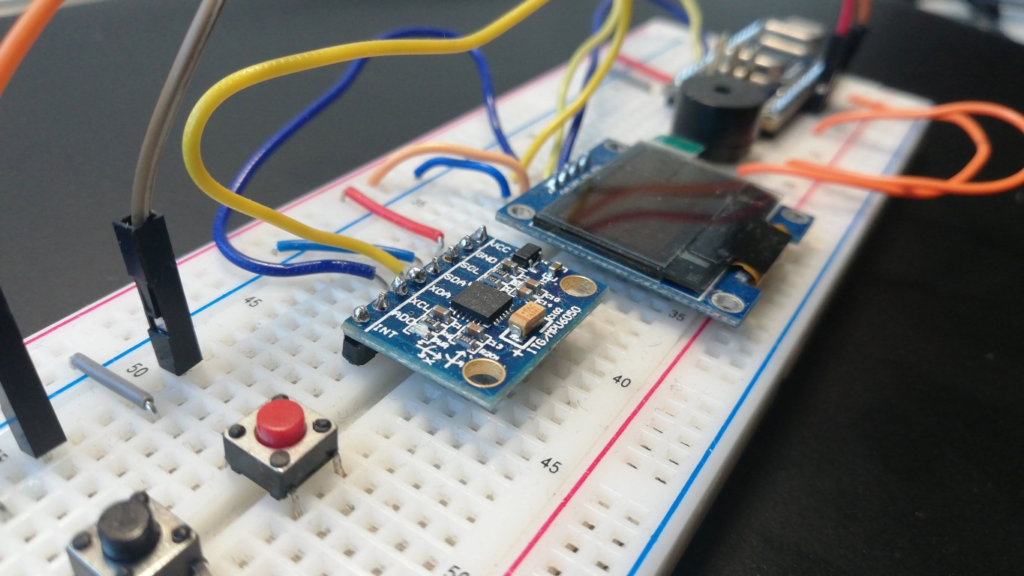
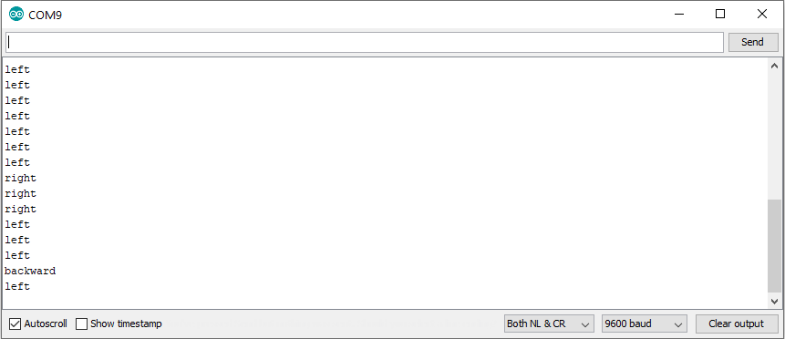
Download this example sketch mpu6050_display.ino and upload it (set the appropriate Processor and Com Port in the tools menu). Open the Serial Monitor (Tools > Serial Monitor) to see if the controller works (tilt the controller):
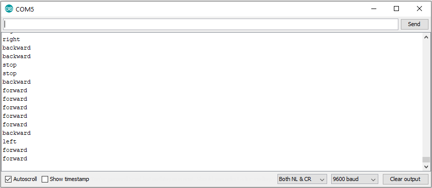
While tilting the breadboard you should see movement indicators passing by on the Serial Monitor and also on the display:
Now continue to step 3 to use the controller with the game.
2. Build controller with phone
(if you just build the MPU-6050 based controller in step 1 you can skip this step and head over to step 3!)
You can use the Accelerometer & Gyroscope sensor from your phone and stream its data to the BLE-Nano over Bluetooth via the Dabble App. The BLE-Nano will be connected to your computer, interprets the data received from the phone and translates that into commands, which it will send to the game (via the USB/serial connection). In this scenario, your phone will be the actual controller, and the Arduino only passes-through the data.
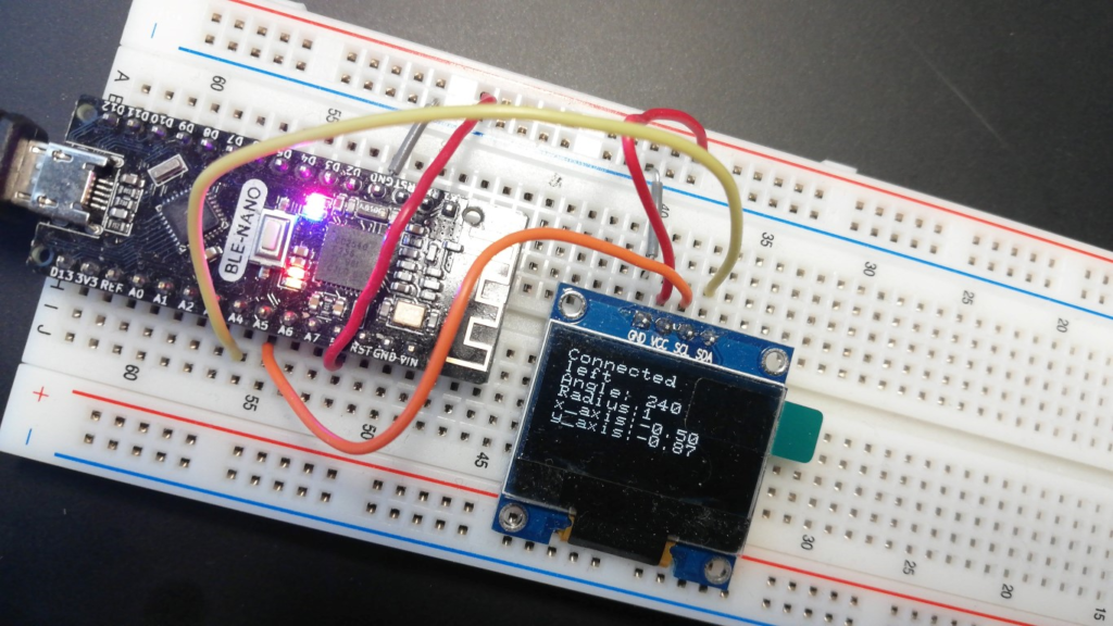
Add the BLE-Nano and the OLED display to the breadboard and connect them to the I2C ports (A4/SDA & A5/SDL) of the Arduino. This has been done in previous assignments too, like practical assignment 1.
Install Dabble on your Smartphone
We will use the Dabble App to communicate with the Nano-BLE. Dabble is available for Android and iOS.
Use example sketch
Download this example Arduino sketch bt_dabble_gamepad_accl.ino and upload* it (set the appropriate Processor and COM Port in the tools menu). If the port does not show a COM… value, you might have to install a driver.
Start the Dabble App on your phone, select Gamepad, via the icon ![]() select Accelerometer Mode. Then make the Bluetooth connection.
select Accelerometer Mode. Then make the Bluetooth connection.
Open the Serial Monitor (Tools > Serial Monitor) to see if the controller works (tilt the controller):
While tilting the phone you should see movement indicators passing by on the Serial Monitor and also on the second line of the display:
* Having trouble uploading? Make sure the Bluetooth connection is disconnected! If uploading takes long, disconnect the USB cable, then reconnect.
3. Realize communication with the game controller in the game
Communication via a serial connection can be realized with the jSerialComm library. We will first add that to the project. You can continue with the project of the previous assignment.
Add the jSerialComm library
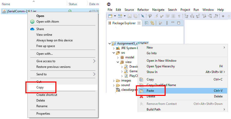
Download the library as a .jar file here. Copy the .jar file in the Windows Explorer. In Eclipse, right-click the main project folder and paste it into that folder:
Next, add the library to the build path: right click it in the Package Explorer, and select Build Path > Add to Build Path. Now you can use the library in your project.
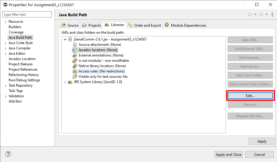
To add the Java Documentation (JavaDoc) of this library also, right-click the library again, select Build Path > Configure Build Path. Switch to the tab Libraries, select Javadoc location and press Edit to add the path https://fazecast.github.io/jSerialComm/javadoc:
To use the library we can add a few methods to the main userinterface class (GameUI). To facilitate communication we must:
- Connect: setup a connection to the COM port and listen for incoming data.
- Receive: process incoming data and act on it
- Send: send data to the COM port
For each of these tasks we will provide you with methods and a necessary class variables. These methods and class-variables are given in this text file communication.txt, which you can download/view here. Copy the variables and methods from that file into the main userinterface class (GameUI). Make sure you copy everything at the right spot: variables at the top of the class, methods at the bottom. Format the code afterwards, as while copying the code might be a bit messy (right click > Source > Format).
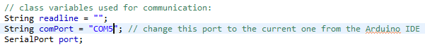
Add a call to the connect() method at the end of the constructor of GameUI. This will initiate the connection to the COM-port specified in class variable comPort and start receiving commands.
Connect the Arduino with an USB cable. In the Arduino IDE, check the COM port. In the main userinterface class (GameUI), change the port accordingly:
Make sure the Serial Monitor is not running (there can be only one App communicating with the Arduino at the same time!).
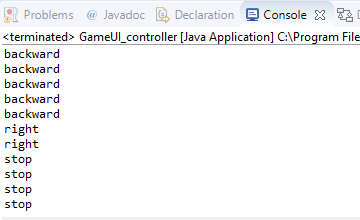
In Eclipse, Run the application. In the Console, you should see incoming texts of the movements you make with the controller coming in:
Add code to the receive() method to act on incoming movements
In the receive() method, the String line contains incoming messages. We can check the content of the message, with an if statement, and then act: eg. call a method of the panel. For a check on movement “left” a design of this code in pseudo code could look like this:
if (line starts with "left")
	call method left() of panel
Now turn this into working code yourself and add that to the receive() method. A hint: the String class (variable line) has a method startsWith(). You will need an “else” part and an additional “if” to check for other movements. Checking just the movements “left” and “right” will be sufficient for now, as those are the directions the basket can go.
Run the game. You should now be able to control the movement of the basket with the controller.
4. Add extras
Choose one or more of the extras (4a-c) to realize (you are free to choose, as long as you do at least one of these). There will be limited help in this assignment for step 4, as we expect you to be able to figure out most of the coding yourself.
4a. Show the score on the display on the breadboard
Send the score to the controller and show it on the (OLED) display.
Add a reference to the GameUI class in the class DrawingPanel. How to do this is explained in the lecture. Then, find the spot where the score is updated (there will be a line with score++; ). At that spot, add a call to the send() method of the GameUI class:
gui.send("Score: "+score);Note in this example the class variable with a reference to the GameUI is gui. Your class-variable might have a different name!
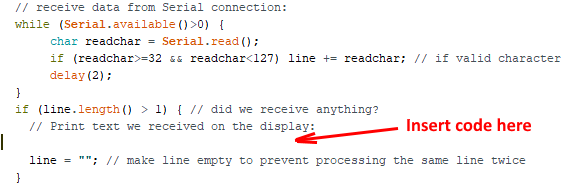
Now on the Arduino side, the sketch must show the score it receives on the display. There is already a part to receive data in the loop() in the example sketch, you can add code there to show the score on the display:
From the code that the game sends:
gui.send("Score: "+score);You can see it is a String, “Score:” followed by a space, and then a number (the score). You can separate these in the Arduino code to print them on two lines like this:
You can use the functions getPart1() and getPart2() to separate the line, these functions are defined at the bottom of the sketch. Use them, eg. to get the first part:
String part = getPart1(line); // get first part of lineAnd put that into a character buffer:
part.toCharArray(buf, sizeof(buf));The variable buf you can then draw on the display at a specific line using the drawString() or draw2x2String() of the display (do not use line 0 or 1). You have used this in previous assignments and there is also an example in the function message().
Repeat these steps for the second part of the line, using function getPart2().
Please note: If you use the Dabble version of the sketch (using your phone as the controller), you must comment-out the lines in the loop() that show the data on lines 2-5 of the display, under the comment // print data to the display
This is because now we will use that part of the display to show the score!
You might also notice that there are garbled or strange characters displayed now and then. If that is the case, switch the gamepad to digital mode, that might resolve this (in accelerometer mode, more data is transmitted which might lead to occasional ‘hiccups’ in communication).
Run the game and check if the score is shown on the display.
4b. Launch Balls with the external controller
Add a button (switch) to the breadboard and use that to launch (extra) balls. Or, if you use your phone as a controller, you can use one of the buttons of the Dabble gamepad, like the “triangle” or “select” button.
It is also possible to add another (tilt) movement to launch balls: eg. if you move the controller forward, launch an extra ball.
For a button, you can use the basic example from the Bounce2 library. Then if the button is pressed (fell), send a message, eg. “launch”:
message("launch");For a move forward (of the the controller) or a button on the Dabble gamepad you can simply add another check in the receive() method of GameUI.
An example in pseudo code:
if (line starts with "forward")
	call method newBall() of panel
This should be sufficient for you to add the code yourself. If the message you send is “launch” you should of course check for that.
Check if launching balls with the controller works.
4c. Add vibration or sound effects
You can only add vibration effects if you have the module with the vibration motor. An example of how to use the vibration motor can be found here. Use this to add a vibration effect for not-catching a ball (fail sound in game) and/or catching a ball (ding sound).
Sound effects (Buzzer)
The buzzer was used in this tutorial. Use what you learned there to add sound effects to the game. Realize sound effects for not-catching a ball (fail sound in game) and/or catching a ball (ding sound).
Summary
Today you have written code in both Java (Eclipse) and C++ (Arduino) and learned how to use an accelerometer/gyroscope sensor. You also learned how to communicate between an Arduino and an App in Java. In addition, you have learned coding yourself, with less explanation of the basics.