Introduction to Arduino and programming . There is also a “quick walk-through video” of this tutorial. My practicals which use this tutorial have an introductory presentation (pdf).
Further directions:
- If you are new to using an Arduino, maybe watch some of the intro video’s first.
- For more tutorials on distance sensors, including various applications, look here.
- You can buy this sensor here.
- Look here if you would like to use the Raspberry Pi Pico with this sensor (code in Python).
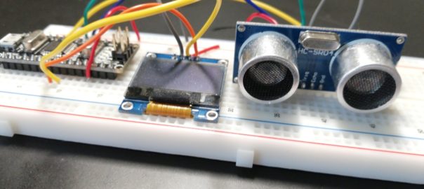
We will build a distance meter in this tutorial. It uses an ultrasonic distance sensor to sense the distance to an object nearby.
It consist of the following steps:
- Connect and test the OLED display
- Connect and test the Ultrasonic sensor
- Add an alarm depending on the distance
- Add comments to the code
1. Connect and test the OLED display
The 0.96 inch OLED Display (128*64 pixels) is an i2c module, which makes it easy to connect as it has only 4 wires. It is assumed you have installed the Arduino IDE and have some basic understanding of using electronics and wiring a breadboard. If not, watch this intro first.
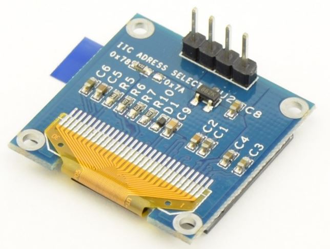
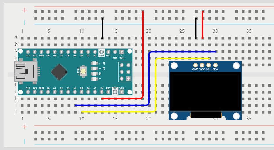
Please take great care: pins on your display might be in a different order! the one below has GND-VCC-SCL-SDA, but yours might be different!
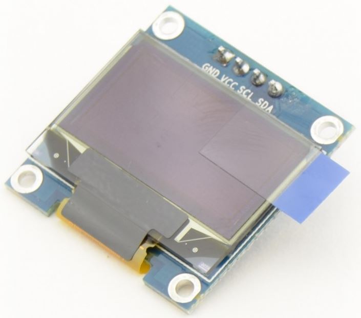
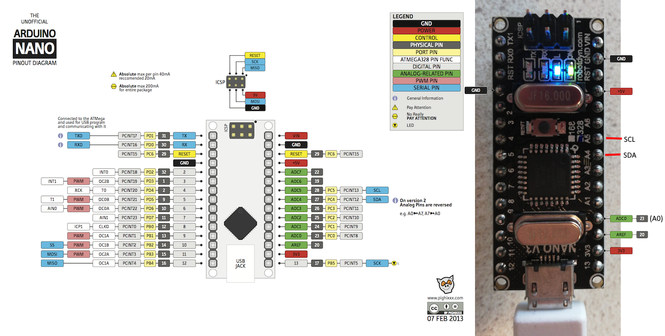
To use this display, you can connect it to power (GND and VCC, it can be either 3.3 or 5V) and connect the SDA and SCL pins to the SDA (A4) and SCL (A5) pins of the Arduino. These are hardware i2c pins:
Display:    Arduino:
GND         GND
VCC         5V
SCL         SCL (A5)
SDA         SDA (A4)
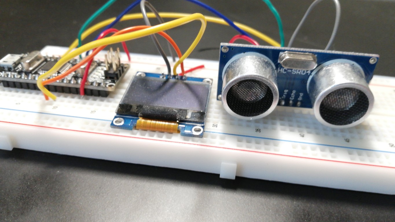
You can mount this display directly onto a breadboard and connect the wires (double check the pins with the table above!). Check the second picture below to see the wiring properly:
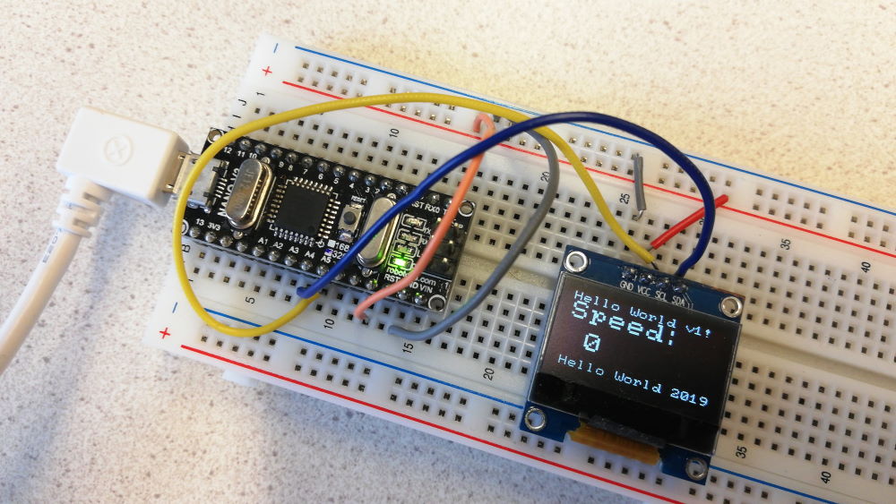
Open the image in a new tab if it does not appear properly (right-click > open in new tab).
View a simulation on Wokwi of this part of the project.
Download example sketch
To test this display, you can use this example sketch: oled_display_distance.ino. Open it in the Arduino IDE. You might get a question that the file needs to be inside a sketch folder. That’s fine, so click Ok. Please be aware that the sketch will then be saved in your Download folder. If you do not want this, Select File > Save As to save it to another folder, for instance the Documents\Arduino folder.
The sketch uses the U8g2 library, which you must install before you use this sketch: In the Arduino IDE, select Tools > Manage Libraries, then search for “U8g2” and install the library (the one “by oliver”).
Next, connect the Arduino to your computer with a USB cable.
Before you upload the example sketch to the Arduino, configure the Arduino IDE to use the correct setting for the type of Arduino you use: under the Tools menu, check the board settings:
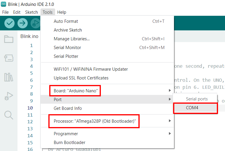
The Port can be any active Port (eg. COM1-12, or on Mac OS something like “/dev/tty.usbmodem…” or “/dev/tty.usbserial-…” ). There should be one or more ports you can select here. If there is one port, select that. If there are multiple, remove the usb-cable from your computer and then check the list of ports again. The one that disappeared is the port for the Arduino. Reconnect the usb-cable and select that port. If nothing happens, or none of the ports work, you might have to install the CH340 driver before you can use the port. Other troubleshooting options are here.
Make sure “ATmega328P (Old Bootloader)” is selected at “Processor”. (However, if you use the BLE Nano, you should use the regular “ATmega328P”).
Upload the example sketch
Now upload the sketch (press the Upload button ![]() ) to transfer the sketch to the Arduino and run it. The display should show some text messages and the value of the variable
) to transfer the sketch to the Arduino and run it. The display should show some text messages and the value of the variable distance. If things go wrong, checkout the troubleshooting options.
To display values of variables with this display in a simple manner, you might need code like this:
display.drawString(0,0,"Distance:");
display.setCursor(0, 1); // go to next line
display.print(distance);
This shows the message “Display:” on line 0, then displays the value of variable display on the next line. The example sketch uses a slightly more advanced way to display the value in a larger font size. Can you find that in the function loop()?
More info about displays
- u8x8 library reference (all methods of the display like the drawString() method are explained in detail here)
- More tutorials for displays on this site.
2. Connect and test the Ultrasonic sensor
This part of this tutorial introduces the HC-SR04 Ultrasonic sensor. Disconnect the USB cable before you continue.
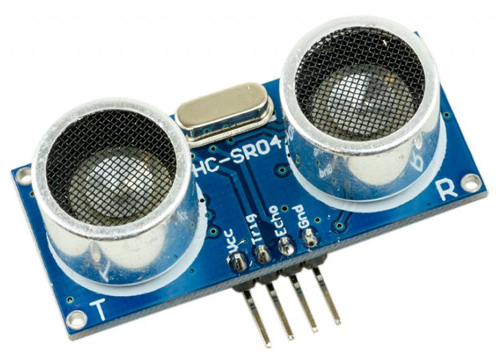
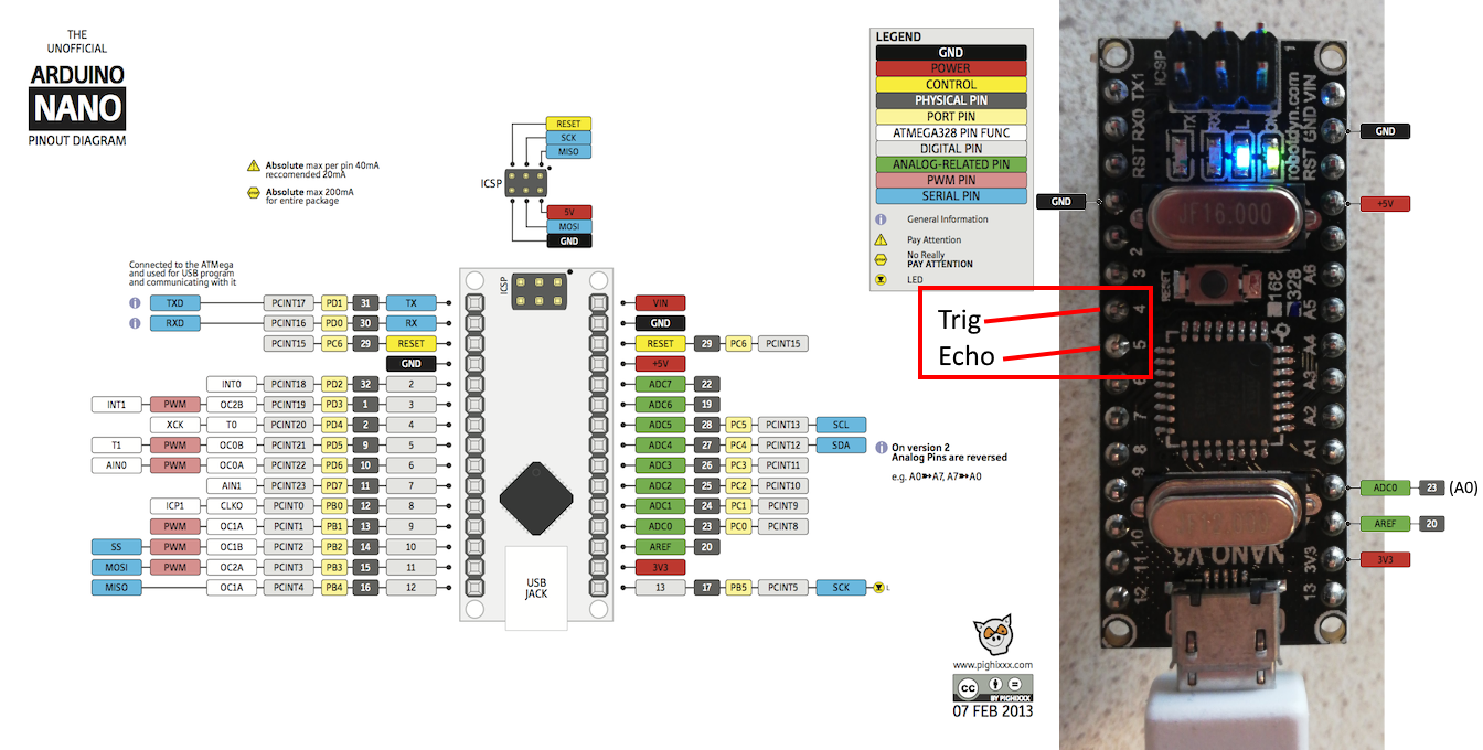
To use this sensor, you can connect it to power (GND and VCC, this must be 5V) and connect the Trig and Echo pins to pin 4 and 5 of the Arduino:
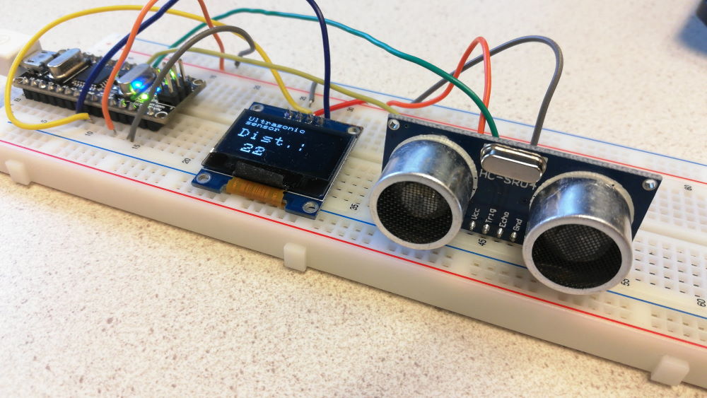
You can mount the sensor directly onto a breadboard:
Download example sketch
To test this sensor, you can use this example sketch: ultrasonic_sensor_with_display.ino. Open the sketch in the Arduino IDE. The sketch uses the Newping library, which you must install before you use this sketch. In the Arduino IDE, select Tools > Manage Libraries, then search for “Newping” and install the library.
Check the sketch
Before you upload the example sketch to the Arduino, verify the lines with #define TRIGGER_PIN and #define ECHO_PIN are set with the correct pins (4 and 5):
#define TRIGGER_PIN  4  // Arduino pin tied to trigger pin on the ultrasonic sensor.
#define ECHO_PIN     5  // Arduino pin tied to echo pin on the ultrasonic sensor.
Next, hook up the Arduino to your computer with the USB cable. Configure the Arduino IDE to use the correct setting for the type of Arduino you use: under the Tools menu, check the board settings:
The Port can be any active Port (eg. COM1-12). After you have connected the USB cable and the Arduino has power, there should be one option you can select here. If you use the regular Arduino Nano, make sure you have selected the ‘ATmega328P (Old Bootloader)’ at “Processor”. (for the BLE-Nano, select “ATmega328P”).
Upload the sketch
Run the sketch (press the Upload button  ). The display should show the distance as read by the sensor. If you do not use a display, you can see the distance in the serial monitor, which you can start via the
  icon in the top right corner.
If things go wrong, checkout the troubleshooting options.
Now find the line of code which looks like:
unsigned int distance = sonar.convert_cm(sonar.ping_median(5));This is the line which reads the distance value from the sensor and assigns it to the variable distance. It uses the method ping_median(5), which will do 5 readings in a short time and takes the median of the five readings and returns that value. This will improve the accuracy of the readings.
More information about distance sensors
- More information about the library NewPing (including descriptions of all methods).
- Find more examples using distance sensors on this site.
- makerguides.com: How to use a HC-SR04 Ultrasonic Distance Sensor with Arduino
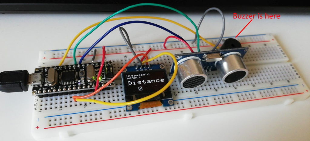
3. Add an alarm depending on the distance
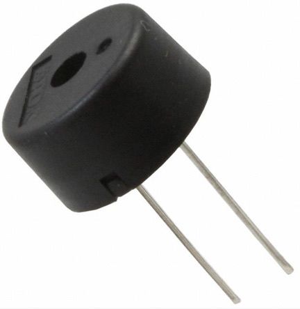
We are going to use a buzzer, which is a small device that can generate tones. There are different types, as explained in this video:
Function wise they all work the same: a Pulse-Width-Modulated (PWM) signal is sent to it to generate the sound. Usually, the + pin of the buzzer is indicated by a + sign on the housing or on the bottom. If it is not, the longest leg is the +. If there is no visible indication of a + pin, just connect it. You cannot break it by connecting it wrong, just give it a try. If it does not work, reverse the connection and try again.
Connect the + pin of the buzzer to pin 9 of the Arduino (use pinout diagram) and connect the other pin to the (blue) GND track of the breadboard. The buzzer must be connected to a PWM pin on the Arduino. Pin 9 is a PWM pin. More on PWM.
Download the sketch sound_active_buzzer_example.ino, connect the usb cable and upload the sketch. It should play a tune. You can also try this example sound_tune_happy_birthday.ino if the other one does not work.
If you are already an experienced programmer, you should be able to combine the previous example (from step 2) with this one and make an alarm dependent on how close an object is. But combining two sketches might be a bit much for a start, so we have done this for you. The only thing we left out is the part which determines when the alarm has to sound. (This will be an if statement with a call to a function).
The combined example can be downloaded here: ultrasonic_sensor_warning.ino. Browse through the code, and check for parts you recognize from the previous examples. Try the example (upload it). As you may notice, it plays a short tone at the start. Can you find the line of code which does this? It is the last line in the setup() function. This is the line:
playTone(C, 16 * tempo ); // play a C for 16 beatsIf this way of generating sound with the playTone() function does not work in your situation, try it with the basic tone() function build into the Arduino core (more info):
tone(speakerOut, 2000, 500);To make an alarm, two things have to be done:
- Determine if an alarm has to be sound (with a condition)
- Make the alarm sound
Determine if an alarm has to be sound (with a condition)
In the loop(), near the end, find this line of comment:
// something nearby?After that line, add an if-statement, with the next line of comment inside it:
if (condition) {
     // sound alarm
}
If something is close, the variable distance is smaller than a certain value. So an example of the condition is distance < 100. Add this to the code (replace the ‘condition’ between the brackets of the if-statement).
Make the alarm sound
Inside the if-statement, add the line of code which plays a tone (copy it from the last line of the setup() method). Make it play another tone, so not a C. You can find a list of the tones that can be played at the top of the sketch. If you are using the basic tone() function, adjust the frequency and the duration to generate a different tone (use this info).
Adjust the comment at the end of that line so it matches the code.
Now test the sketch (upload it). Does it work? Adjust the distance checked for in the condition. It should NOT be a meter (100cm).
A small fix
You might notice that sometimes it gives a false warning, when a 0 value is measured. A 0 value might be the result of an error, or because the reflected signal is not returned properly because there is nothing in sight (do you know how an ultrasonic sensor works? Check out the slide in the presentation about this).
The condition must be adjusted so it does not sound an alarm if the distance is 0. We can use an AND condition for this: distance > 0 AND distance < x. (x is the value you use in your condition). In both C and Java, the boolean AND operator is a ‘&&‘ symbol. So the condition will be: distance > 0 && distance < x. Modify your code accordingly. Do not forget to replace the x with your value for the distance.
4. Add comments to the code
Add more comments to the part of the code that you added/modified. The comments should explain, in your own words, what this code does. Use multi line comments or single line comments. Some examples:
/*
Example of a multi line comment.
This is the second line of the comment.
*/

// Example of a line of code with comment at the end of the line:
Serial.println("Start of distance measurement"); // display text on serial output
At the top of the sketch, add general comments. The first line of comments should contain your name and student number. Add at least one more line which explains the general meaning of the sketch as a whole (what does it do?).
Summary
With this tutorial you have familiarized yourself with building an electronic circuit using a breadboard and you have used the Arduino IDE to program the Arduino with a sketch.
In addition, you have learned the following:
- Adding components like a display and a sensor to a breadboard and wiring them
- Using an example sketch to test the components
- Use and setup libraries
- Add code to an existing sketch
- Explain and document code by adding comments to code