This tutorial describes how to build an electronic circuit with an RGB LED (a LED that can change color), and change its color using an App. It also demonstrates two-way communication over Bluetooth LE between an App built with App Inventor and the BLE-Nano board. The BLE-Nano board is basically an Arduino Nano with an added onboard Bluetooth LE module. App Inventor is a very user-friendly and easy way to build Android apps, using a designer and blocks-like programming.
This tutorial is very similar to this tutorial, which describes setting up (one way) communication over Bluetooth LE between an App built with App Inventor and a regular Arduino Nano using an external HM10 Bluetooth module.
Please check out the Troubleshooting section at the end of this tutorial if you run into trouble.
The BLE-Nano board we use in this tutorial (sold here) is a combination of a traditional Nano with a Bluetooth BLE module, based on the CC2540 BLE Bluetooth chip.
This is the pinout of the board:
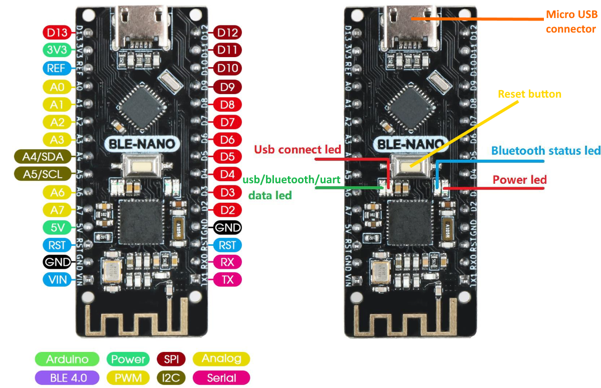
The pinout is the same as the regular Nano.
Build the circuit: add an RGB LED to the BLE-Nano board and test it
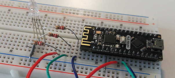
First, build the circuit according to the example given below:
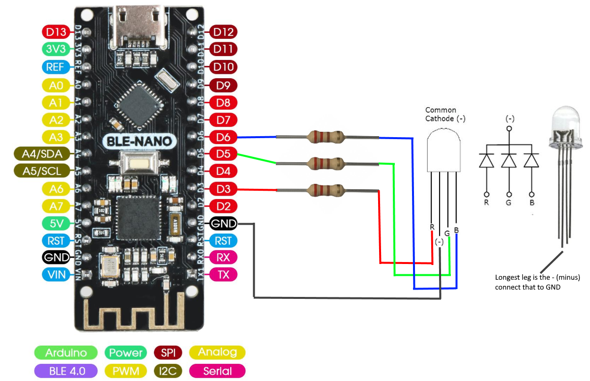
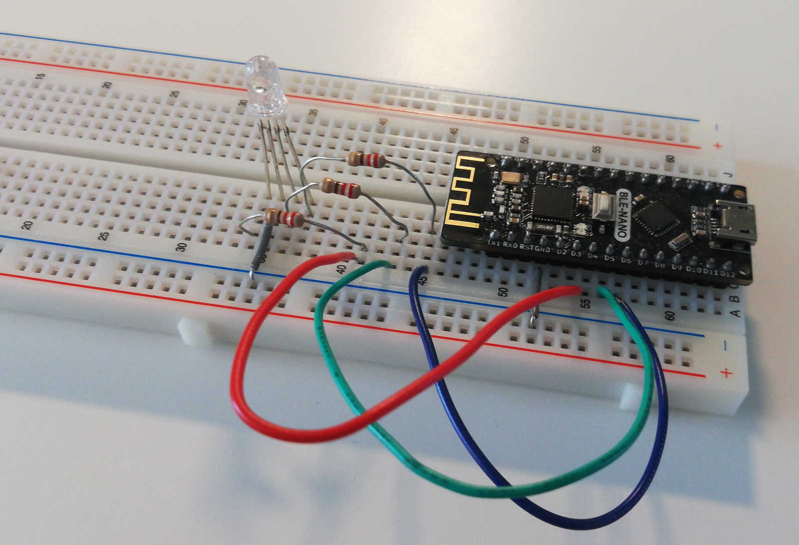
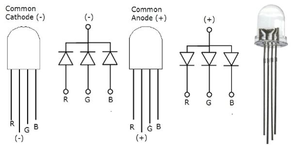
Resistors are 220 ohm (180 or 330 will work also). RGB LED is of type common-cathode.
If using a Common-Anode RGB LED: replace the black wire with a red one and connect that to 5V:
Next, download this example sketch: BT_rgb_led.ino and open it in the Arduino IDE.
Please note: if using a Common-Anode RGB LED: In the code, find the comment “// if you're using a common-anode ...” and use that piece of code instead of the code for the common-cathode LED (comment that out).
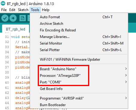
Connect the Arduino to your computer with the USB cable. In the Tools menu, select Board, Processor and Port (the number of your port might differ):
Click the upload button ![]() to compile the code and upload it to the Arduino. After you uploaded the sketch, the LED should blink red-green-blue once, as you can see in the code in the setup(). You can use this to verify whether you connected it properly. If it did not blink, check your wiring.
to compile the code and upload it to the Arduino. After you uploaded the sketch, the LED should blink red-green-blue once, as you can see in the code in the setup(). You can use this to verify whether you connected it properly. If it did not blink, check your wiring.
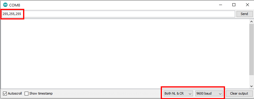
Start the Serial Monitor (Tools > Serial Monitor) and check if its speed is set to “9600 baud” and line ending set to “Both NL & CR”.
Now type 255,255,255 and press Enter, then check if the LED turns on (white). Try other color values, eg. 255,0,0 for red.
Get started with App Inventor and install the demo App
If you are new to App Inventor, you might want to do a ‘getting started’ tutorial first. But this tutorial will take you through the basics of opening and using a ready-build app (but it will not learn you how to create the app).
Take these steps to open the App:
- Download the file
Control_RGB_LED_v4.aiato your computer. This contains the App Inventor project for the App. - Login to App Inventor by clicking the “Create Apps!” icon in the top bar.
- Select Projects, Import project (.aia) from my computer … then click the Choose File button to select the .aia file you downloaded. Click Ok.
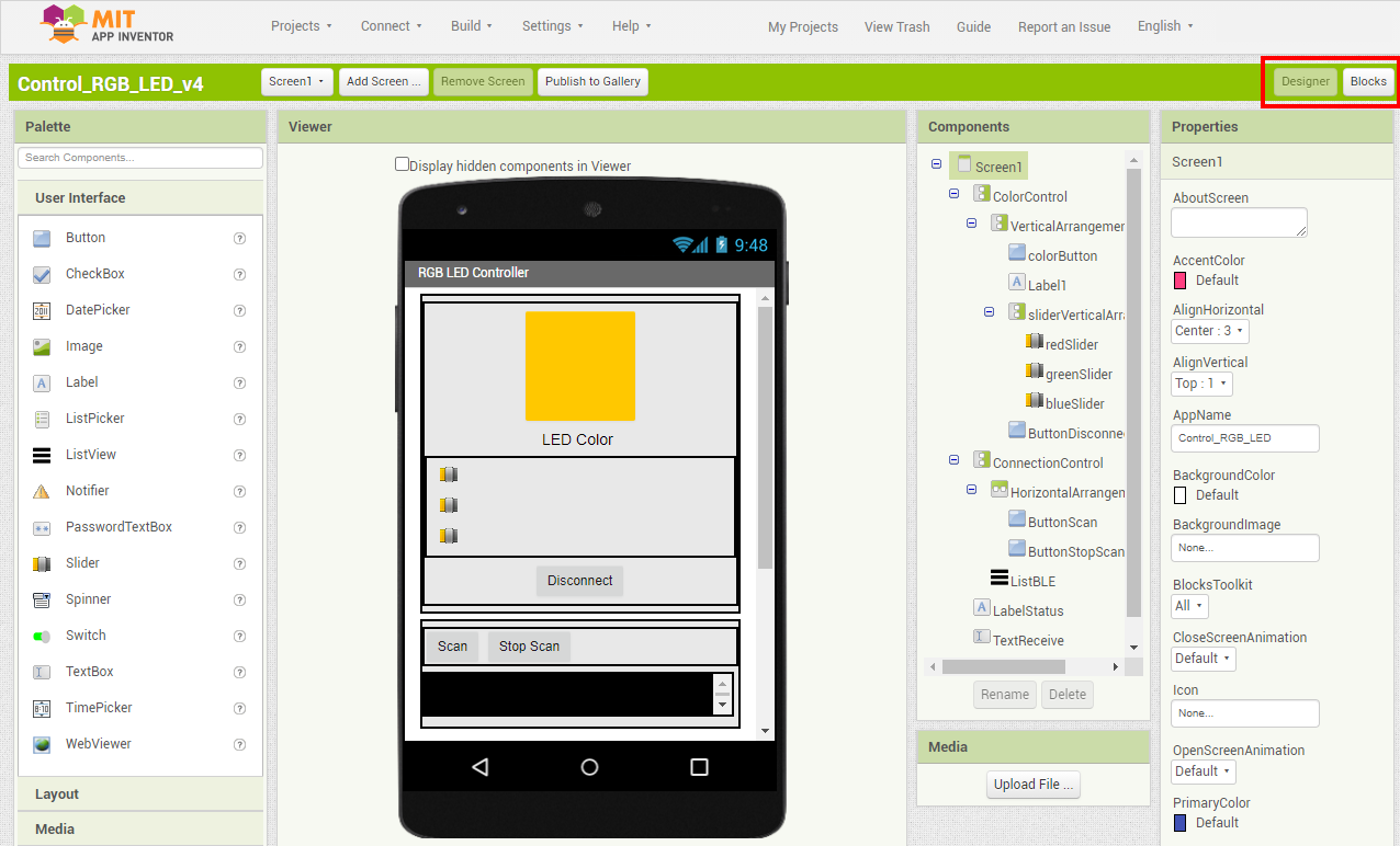
- The project will be loaded and you see something like:
How this environment works will be explained below. But first we will show how to install the App on your phone:
- Install the App Inventor Companion App on your phone (Google Play store/Apple App Store) and start it. (explore these alternative options to run the App)
- In App Inventor, select Connect, AI Companion from the menu. Then on your phone, click “scan QR code” and scan the code on your screen. The App should then launch on your phone (screen 1 below).
You will have to do the last step again if you resume the App at a later time (eg. if you do something else for a while).
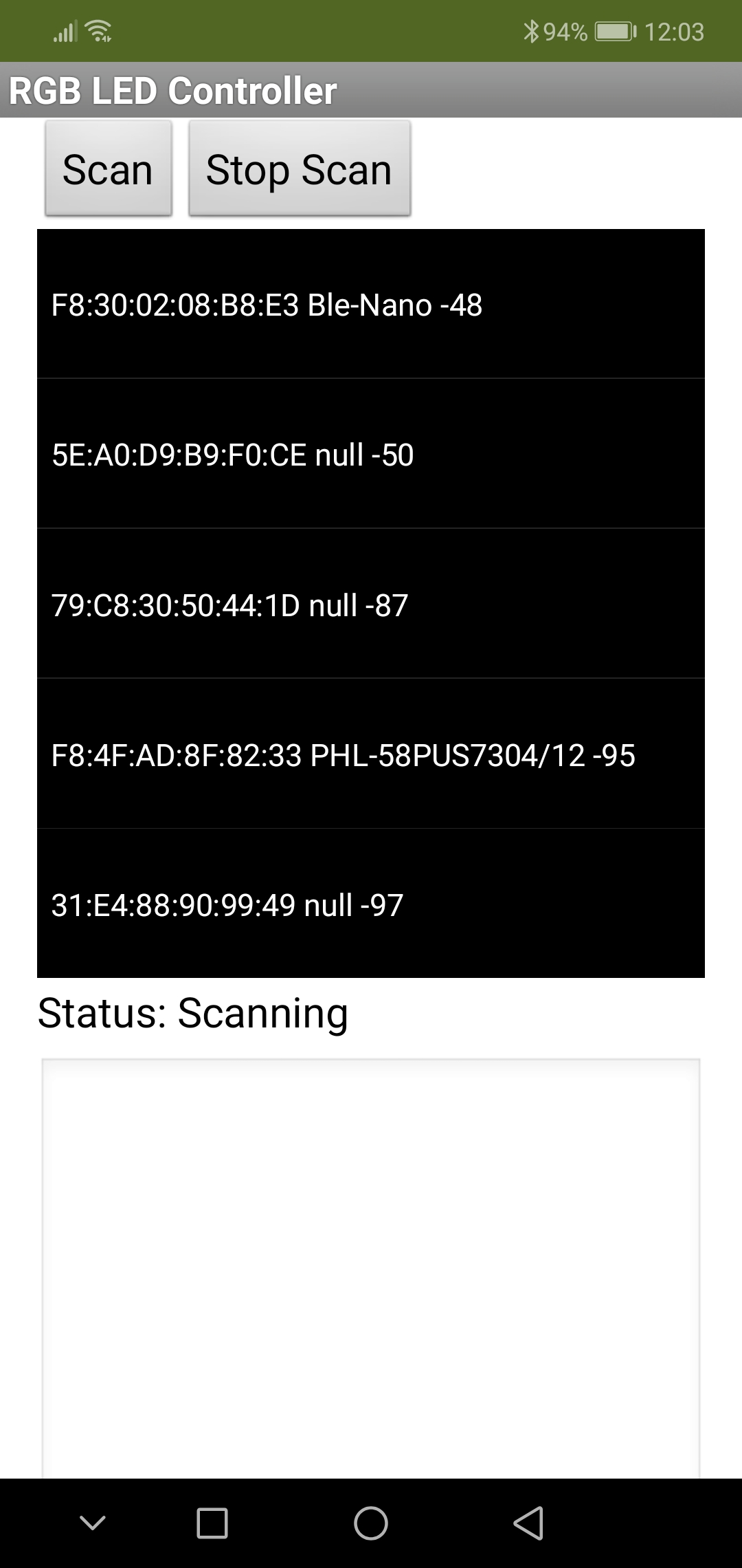
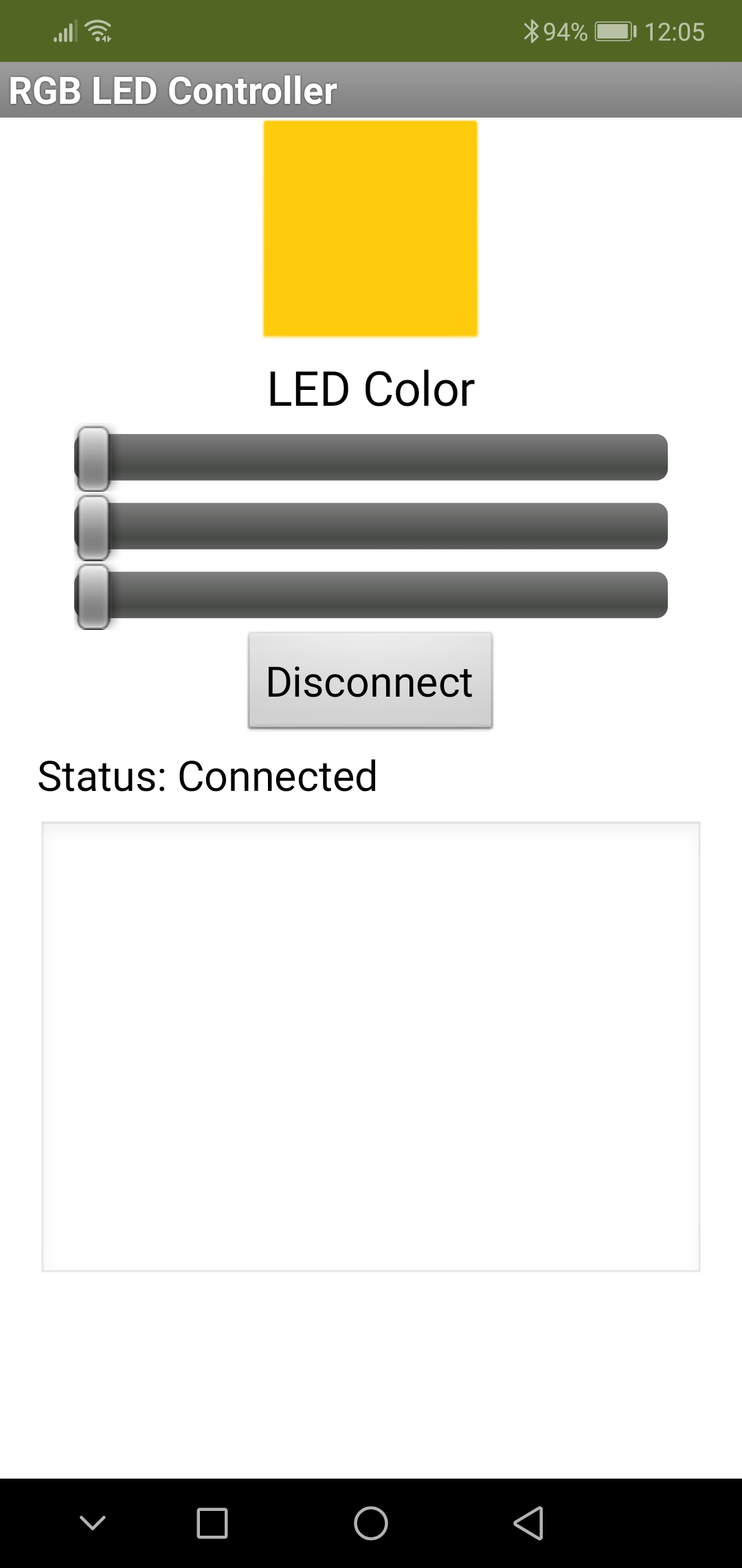
The first time you launch the App, you might have to enable Bluetooth and give the App Location permissions. In the App, select the line with “Ble-Nano” to make a Bluetooth connection with the Arduino. This should switch the App to its mode in which you can change the color of the LED (screen 2 below).
If you drag one of the sliders, the LED should change color, and you should get the HEX value of the color back in the text box at the bottom of the App (screen 3):

Working of the App
Some explanation of how the App was created.
In App Inventor, there are basically two working area’s: the userinterface Designer and the Blocks Editor. You can switch between them using the buttons Designer and Blocks at the top right:
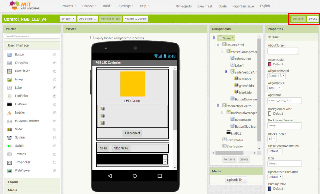
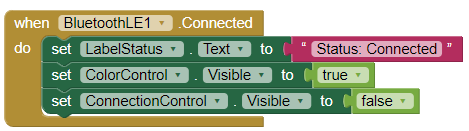
The userinterface consists of all elements that are needed to interact with the user. You can add elements from the Palette at the left side and change properties of the selected elements at the right side. Elements can be organized in Horizontal and Vertical Arrangements (sort of containers) to accommodate a layout. You can find these in the Palette, under “Layout”. These Arrangements can also be shown and hidden when needed. For instance, after a connection is established, we can hide the parts that are used to make a connection, by setting the parameter Visible of the ConnectionControl Arrangement to false. And at the same time, we can show the part that allows to control the color, by making the ColorControl Arrangement visible. This is shown in the last 2 lines of this block (switch to the Blocks Editor to see this yourself):
If you want to create an App that uses Bluetooth, you must incorporate the Bluetooth LE extension. How to do that, is explained here.
How the changed color values are sent via Bluetooth
The color can be changed by dragging the 3 sliders. Each time a slider is dragged its ‘PositionChanged’ eventhandler is called:
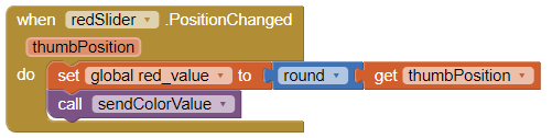
As you can see, this makes a call to the procedure sendColorValue. Which looks like:
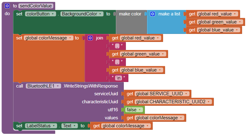
This procedure first shows the new color as the BackgroundColor of the colorButton. So the user can see the resulting color in the userinterface. Then it constructs a String colorMessage, which will contain the full RGB values separated by comma’s and ending in a newline character ‘\n’. This string is sent to the Bluetooth Serial channel with the next call to the method WriteStringsWithResponse of the BluetoothLE1 object.
How this App receives values coming from the Arduino
When texts (Strings) might arrive through the Bluetooth connection at arbitrary intervals, after the connection is established, we must tell the Bluetooth service to register for strings (in purple below):
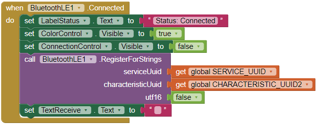
This will make sure the StringsReceived callback will be called each time a String arrives:
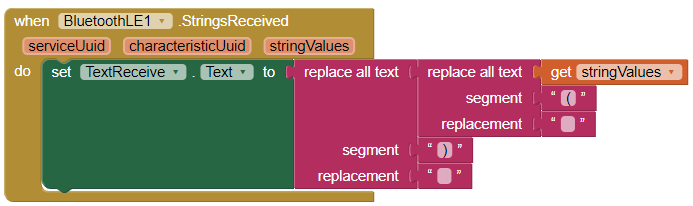
In this block we actually process what is arriving. In this example, we strip the brackets (using the replace all text functions) and show the String in the TextReceive textarea in the userinterface. (We do not actually do much with it, we just show it)
Part 2:
Build your own App: receiving sensor data in an App
Example of how to receive sensor data from a DHT11 temperature sensor in an App and act on it.
In the example above, the Arduino sends the color value back to the App in hexadecimal format and the App displays this in the textbox at the bottom. This is just to demonstrate there is two-way communication. But of course, we can do more useful things, for instance get sensor data from the Arduino and do something with that in the App.
For this we will add a temperature sensor to the circuit:
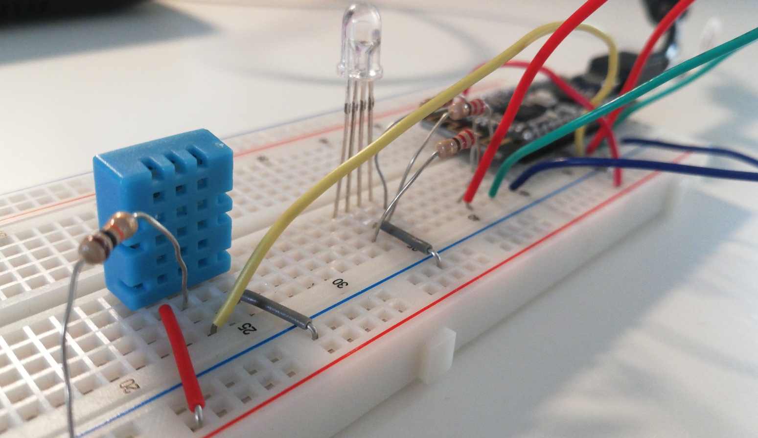
Build that from this tutorial (just the first part, until “Test the sensor”). Test the sensor using the sketch provided there.
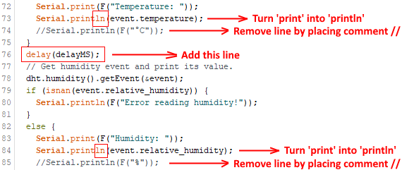
To be able to properly read the values from the lines printed in the sketch, we must adjust the sketch a bit. At the lines indicated below, remove line which prints the unit to make it easier to read the values later. And insert the extra delay for better timing of the Bluetooth communication:
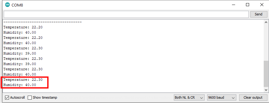
Upload the sketch and check if it shows proper values without the units in the Serial Monitor:
Now close the Serial Monitor.
Now we will build the App step-by-step based on a template which already has all necessary Bluetooth functionality. Download this template DHT11_receive_bt_template.aia and open it in App Inventor. This template incorporates the BluetoothLE extension and some basic userinterface elements to manage connections to Bluetooth devices. More info on extensions.
The remaining part of this tutorial explains building the userinterface and coding the blocks in detail. Are you in a hurry? Or not interested in learning to build the App? The complete App can be downloaded at the bottom of this page.
Add userinterface elements:
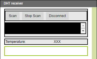
Above LabelStatus (shown in green below) add a HorizontalArrangement (you can find that in the Palette under “Layout”). In that, add two labels. The first one gets “Temperature:” as Text (set that at the Properties). The second one can get “XXX” or you can leave it empty. Name this second one LblTemperature, as we will need this later to show the temperature value. Your userinterface will look similar to:
Program the Blocks:
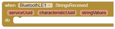
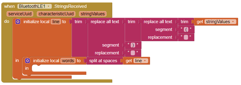
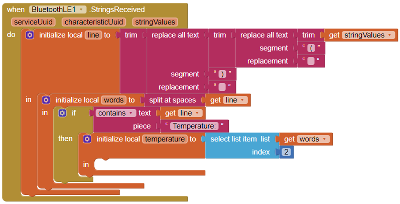
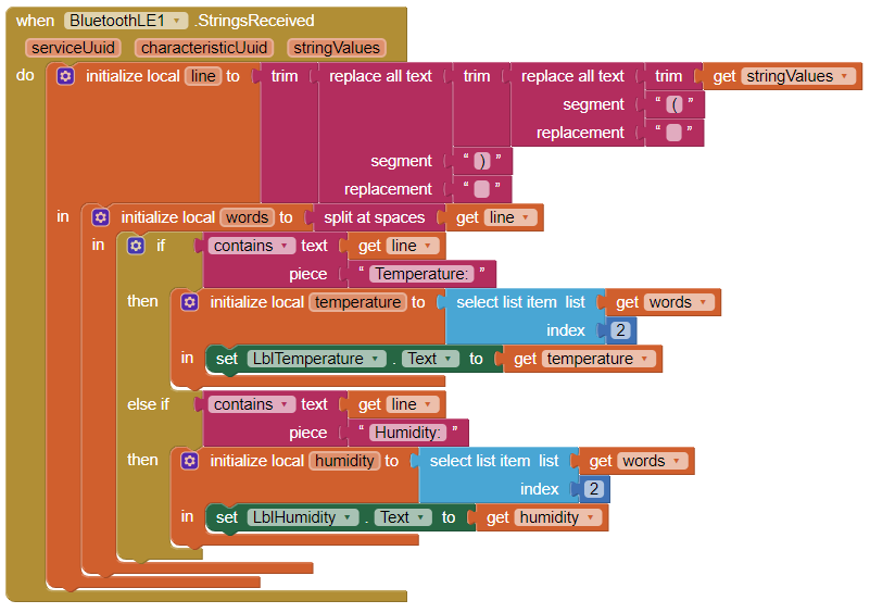
The template already has an empty StringsReceived callback:
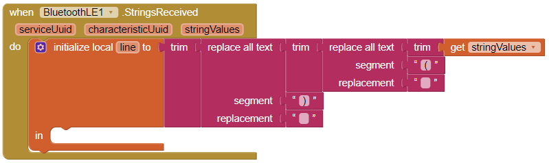
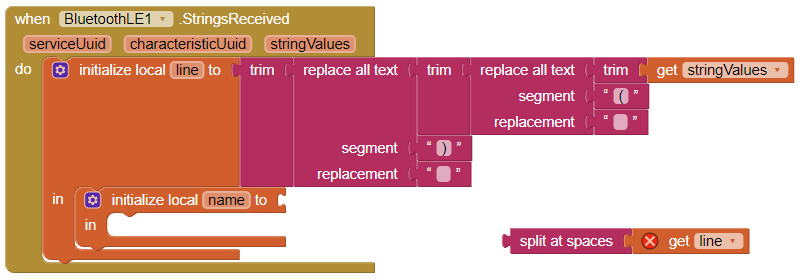
First, filter the incoming stringValues, to remove brackets and unnecessary spaces (trim):
Next, we can add the block to process the received values (in variable line) from the sensor. Lines with received values look like:
Temperature: XX.XXYou can observe the following from this: the temperature value is preceded by “Temperature:”. We can use this to recognize the proper value. The words are separated by spaces. We could split the line into words by using the split-at-spaces method of Texts:
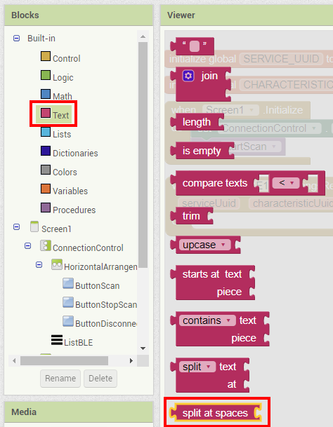
Drag the split-at-spaces method into the editor (you do not have to attach it yet):
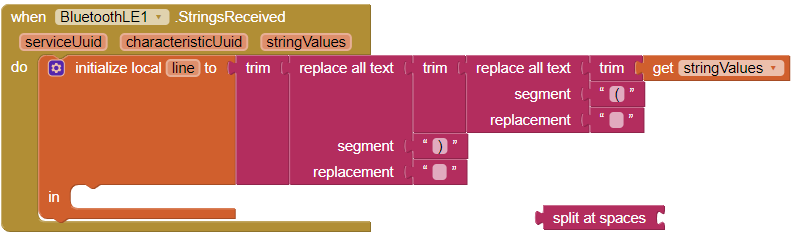
What do we need to split? The line of text that arrives (variable line) of the callback. Click Variables and select the get-method:
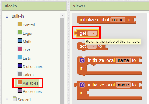
And drag that into the editor, attach it to the split-at-spaces block:

The split-at-spaces block returns a list variable. We must add a local variable for that. Drag the block initialize-local-name-to into the code:
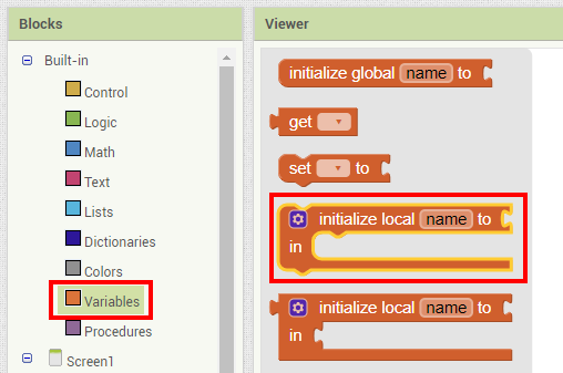
Now drag the split-at-spaces part and attach it to that block:
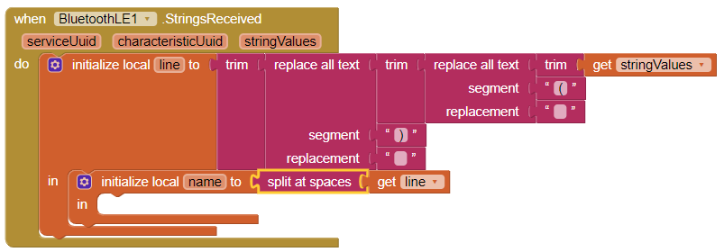
Next, give the list a proper name: we choose words for this, and select the variable line for the get-block:
Checking for temperature values
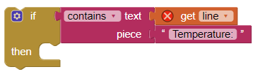
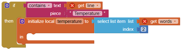
Next, we need to check whether an incoming line contains the word “Temperature:” because only then we need to get the value and show it in the userinterface. Therefore we need an if statement, which looks like:
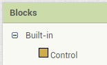
You should be able to add this to the code by yourself now. Look at the colors of the blocks, they correspond with the colors in the Blocks menu, eg. the if-block is light-brown, you can find it in the Control section:
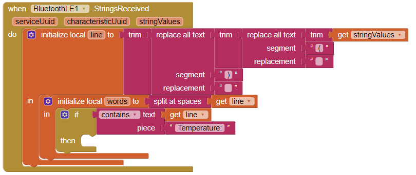
Add the if-statement to the code:
If the line contains the word “Temperature:”, we must get the value from the list of words, it is the second word (index 2 of the list):
Resulting in:
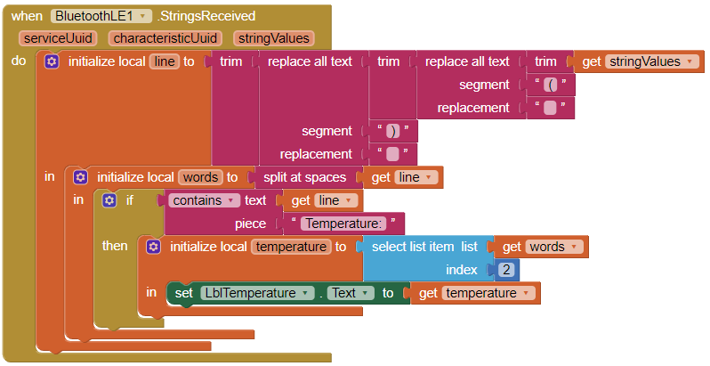
Then we can add the last blocks, to actually show the retrieved temperature in the label:

And this has to go inside the last added piece of code:
Now you can test if this works (rerun the app by starting the companion App on your phone and select Connect > AI Companion in App Inventor).
Finalizing: do the same for humidity
Finally, you must repeat the whole procedure for the humidity value also. Start with adding userinterface elements for that, then program the blocks.
For the humidity part, you can extend the if-block with an else-if section, to add the check for humidity:
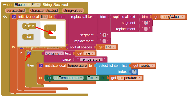
The extended if-block looks like this: (content of the if has been removed for clarity)
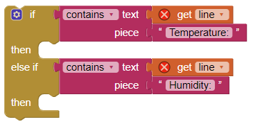
And the complete code now should look like:
Tip: you can copy blocks by selecting them, and then press Ctrl+C. This saves a lot of work. In this case, you can select the purple contains-text block and copy it to the else-if part. Then you only have to change the text behind “piece” to “Humidity:”.
Add a temperature warning:
Because we now get the actual values of temperature and humidity in the App, we can also do things with that. Eg. give a warning when the temperature becomes to high:
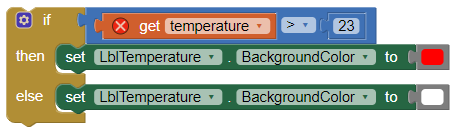
You should be able to figure out what this does and where to put this.
Complete example
If you had trouble programming this yourself, you can download and review the complete example DHT11_receive_bt.aia.
Troubleshooting
Some common issues that might occur:
The Ble-Nano does not appear in the list in the App or a connection cannot be made.
First, try stopping and starting scanning using the buttons in the App. Also, try disconnecting the USB-cable and connecting the Arduino (the Ble-Nano), to restart it. Quitting the App and then reconnecting via Connect > AI Companion in App Inventor also is something you can try. Also make sure the Serial Monitor is not running (the Ble-Nano has its Bluetooth module wired to the Serial port of the Arduino, so if that is connected or communicating with something else, Bluetooth communication will not work). One last thing to try is to reset the Ble-Nano to its default settings as explained here.
Difficulty finding/connecting if there are multiple Ble-Nano’s nearby.
If doing this in the same room with a lot of people having the same Ble-Nano, it might be hard to connect to the right one. You can give your Ble-Nano a unique name to make finding and connecting to it easier. You do this by sending it AT-command to change its name, for example:
AT+NAME=New-Name