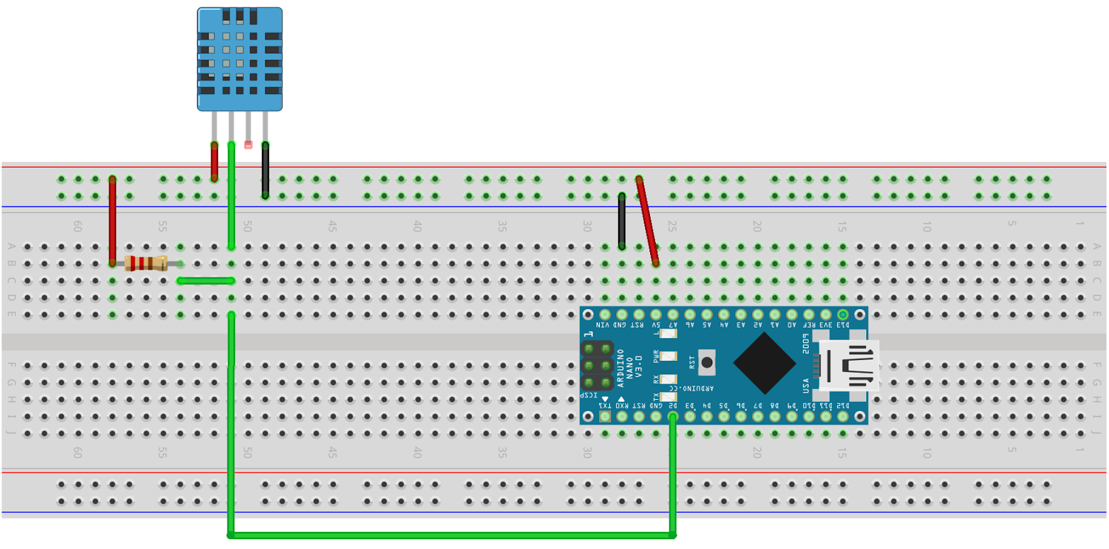
This tutorial uses the Arduino Nano, but you may also use an Arduino Uno. You might need the Arduino Nano pinout diagram or an other diagram for your particular model of Arduino. We are going to use the diagram below to build it. But if you are inexperienced each step is explained in detail.
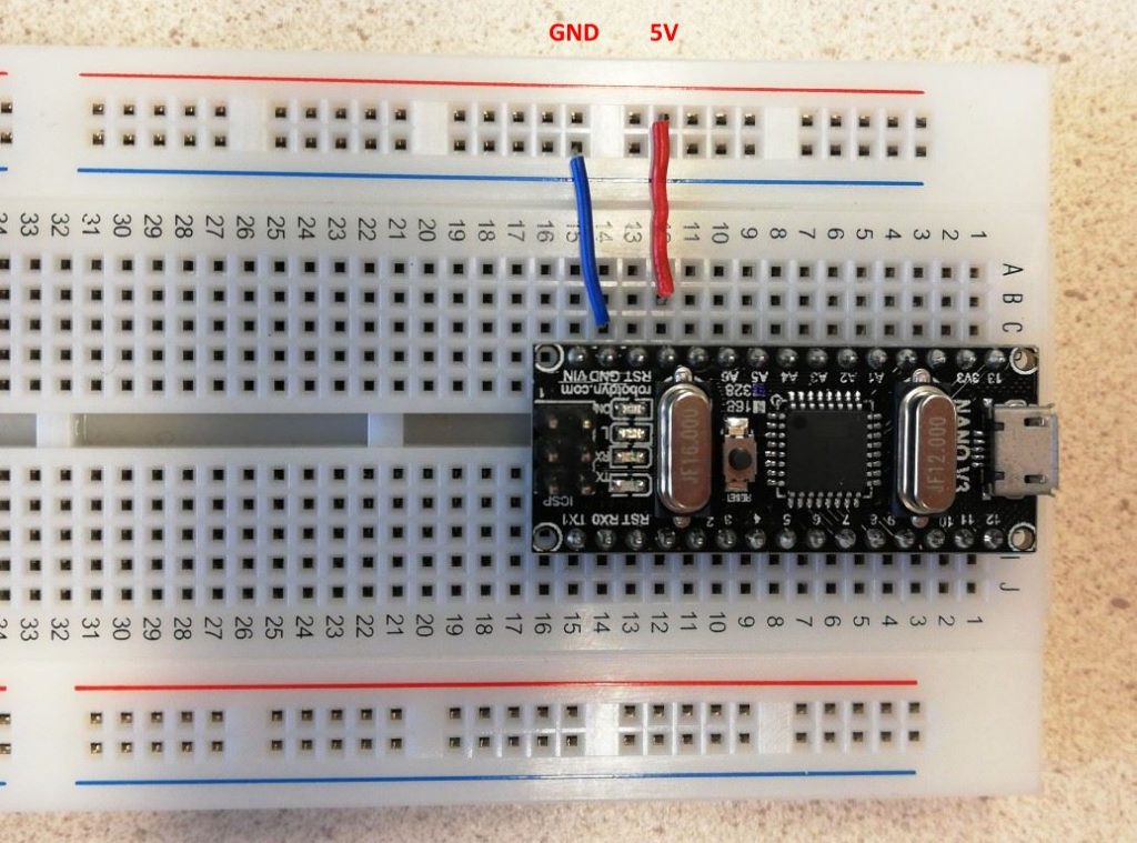
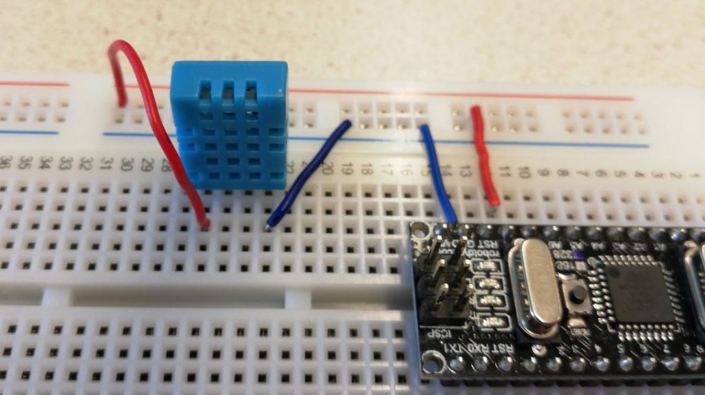
First, connect the 5V and GND from the Arduino to the Red an Blue row of the breadboard:
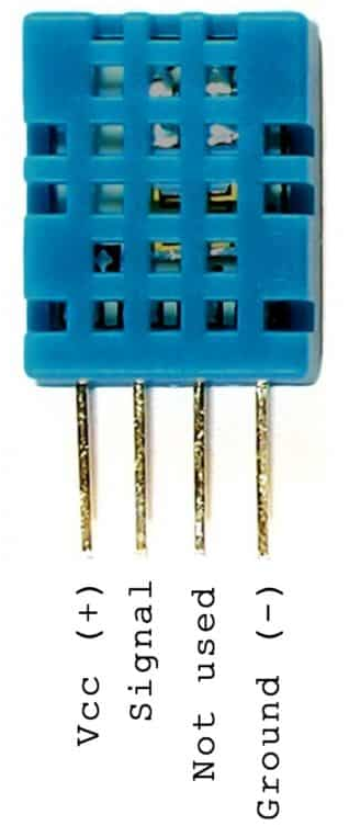
Next, mount the DHT sensor and connect it to the power lines:
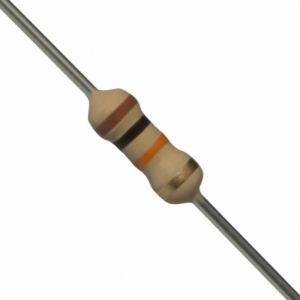
Find a 10K resistor (or get one from teacher). Check the resistor guide if you do not know how to determine what a 10K resistor is. You may also use the Multimeter to check the resistance.
Mount the 10K resistor between the signal pin of the sensor and 5V:
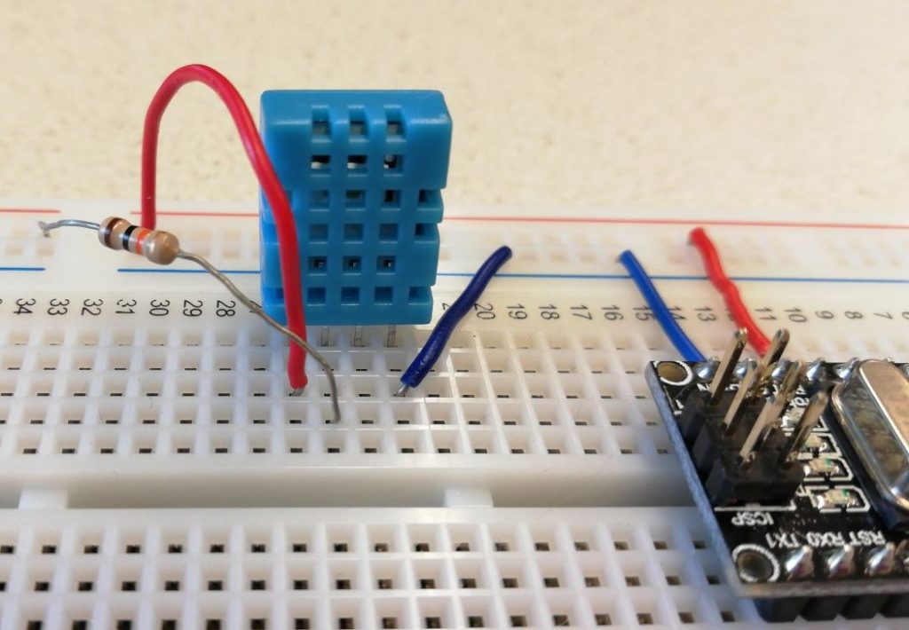
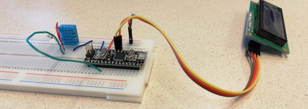
Connect the signal pin from the sensor to the D2 pin of the Arduino:
As you can see I used a few less wires than the diagram on top. But the connections are the same.
Test the sensor
In the Arduino IDE, open the example sketch via File > Examples > DHT sensor library, “DHT_Unified_Sensor”.
If the DHT sensor library is not installed, this example will not be there. In that case, install the libraries “Adafruit Unified Sensor” and “DHT library”. Go to Tools > Manage Libraries, search for the names and install both.
Now you have to change the DHT sensor type in the sketch. Find the #define DHTTYPE lines and make sure the DHT22 has comments in front, and remove the comments in front of the the DHT11 line:
// Uncomment the type of sensor in use:
#define DHTTYPE    DHT11     // DHT 11
//#define DHTTYPE    DHT22     // DHT 22 (AM2302)
//#define DHTTYPE    DHT21     // DHT 21 (AM2301)
Also check if the line which defines the DHTPIN has the right pin number (the pin you connected the signal line to):
#define DHTPIN 2
Save the sketch (in the folder Documents\Arduino). Connect an USB cable. Check the connection settings (under the Tools menu, select the proper Board type, at “Processor”, make sure the proper boot loader is selected and select the COM port). Upload the sketch. Open the Serial Monitor and check whether correct values are displayed. It should look like:
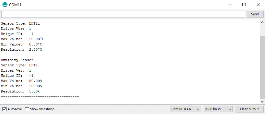
Temperature and Humidity values should refresh about every 1-2 seconds. Breathe close to the sensor, the values should rise.
Add display
Before you connect anything, unplug the USB cable from the Arduino.
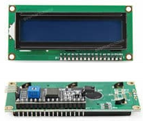
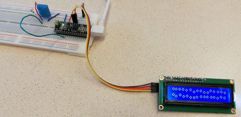
We are going to connect an HD44780 I2C LCD display. But it is also possible to use another display.
Connect 4 male-female jumper cables to the display:
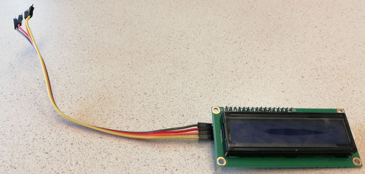
Display:Arduino:
GND	GND
VCC	5V
SDA	A4
SCL	A5
Connect the wires to the breadboard: GND and 5V of the display to the blue and red power lines of the breadboard and SDA to A4 and SCL to A5:
Test the display
For this display, install the library “hd44780” via Tools > Manage libraries. (search for “hd44780”, then scroll down).
The example below is based on an old example, it might not work with the “hd44780” library. Instead, try one of the examples from the library via File > Examples.
Reconnect the USB cable. Download this sketch LCD_HD44780_i2c_hello_world_example.ino and upload it. It should first display “Hello, world!” and “AppDev example” on the second line, and then start some moving balls animation:
There is a change you do not see anything. Then read on.
Troubleshooting the display
Using a small screwdriver adjust the potmeter (the small blue box) on the back of the display to change the backlight. Sometimes the backlight is too high or too low to see anything on the display. It is also possible your display uses a different I2C address. Find this line in the sketch:
LiquidCrystal_I2C lcd(0x27,2,1,0,4,5,6,7); // first parameter is address, can be 0x27, 0x3F or 0x38Change the first parameter into one of the other addresses listed in the comment (0x27, 0x3F or 0x38). After changing, upload the sketch to test with the new address. You might have to try this 2 times to get the address right.
If the display still not works and you tried with these 3 different addresses, resort to general troubleshooting: (re)check all wires and see if they are connected to the proper pins. Then start over with trying the 3 different addresses.
If it still is not working, ask for help or get a replacement display.
Show temperature and humidity on the display
Now combine both examples to show the temperature and humidity on the display. Save the example “DHT_Unified_Sensor” with a new name (use File > Save As), eg. “DHT_Display”.
To make this work, you have to copy the essential parts from the hello world example of the display (display-code) to this new sketch. We will show how this can be done.
In the top part of the display-code, find the included libraries, the definition of constants and the global variable ‘lcd’:
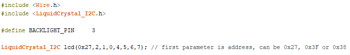
Copy this to the top-part of your new sketch (we refer to it as “DHT_Display” from now on), above the setup() function.
Next, in the display-code find the lines which initialize the display:
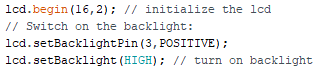
Copy these into the setup() function (put them at the end).
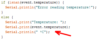
In the loop() function of the display-code, we can find the calls to the functions lcd.home(), lcd.print(...), and lcd.setCursor( 0, 1 ). We will use these to print the temperature on the first line of the display, and the humidity on the second line.
To print the temperature to the display we can use this code (you can copy this):
lcd.home(); // set cursor to 0,0 (first character on first line)
lcd.print("Temp: ");
lcd.print(event.temperature);
And insert this at the spot where the temperature is printed:
To print the humidity to the display we can use this code (copy it):
lcd.setCursor (0,1);        // go to start of 2nd line
lcd.print("Humidity: ");
lcd.print(event.relative_humidity);
Insert this at the spot where the humidity is printed.
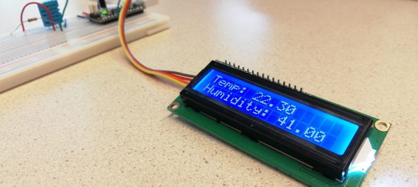
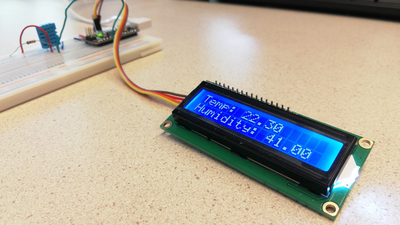
Now test the sketch, it should now show the temperature and humidity on the display:
Challenge: connect to Wifi, publish values on ThingSpeak
As an extra challenge, you could connect the sensor to Wifi using an ESP8266 module and publish the sensor values online.
First, add a ESP8266 module and set it up (make sure it can connect to Wifi). Follow step 1 of this guide to do that, then return to this article.
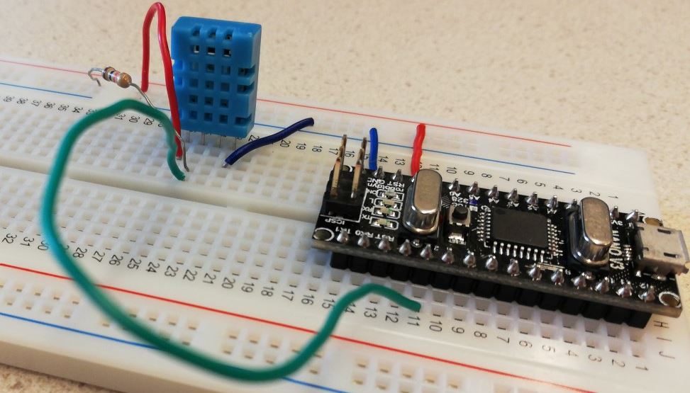
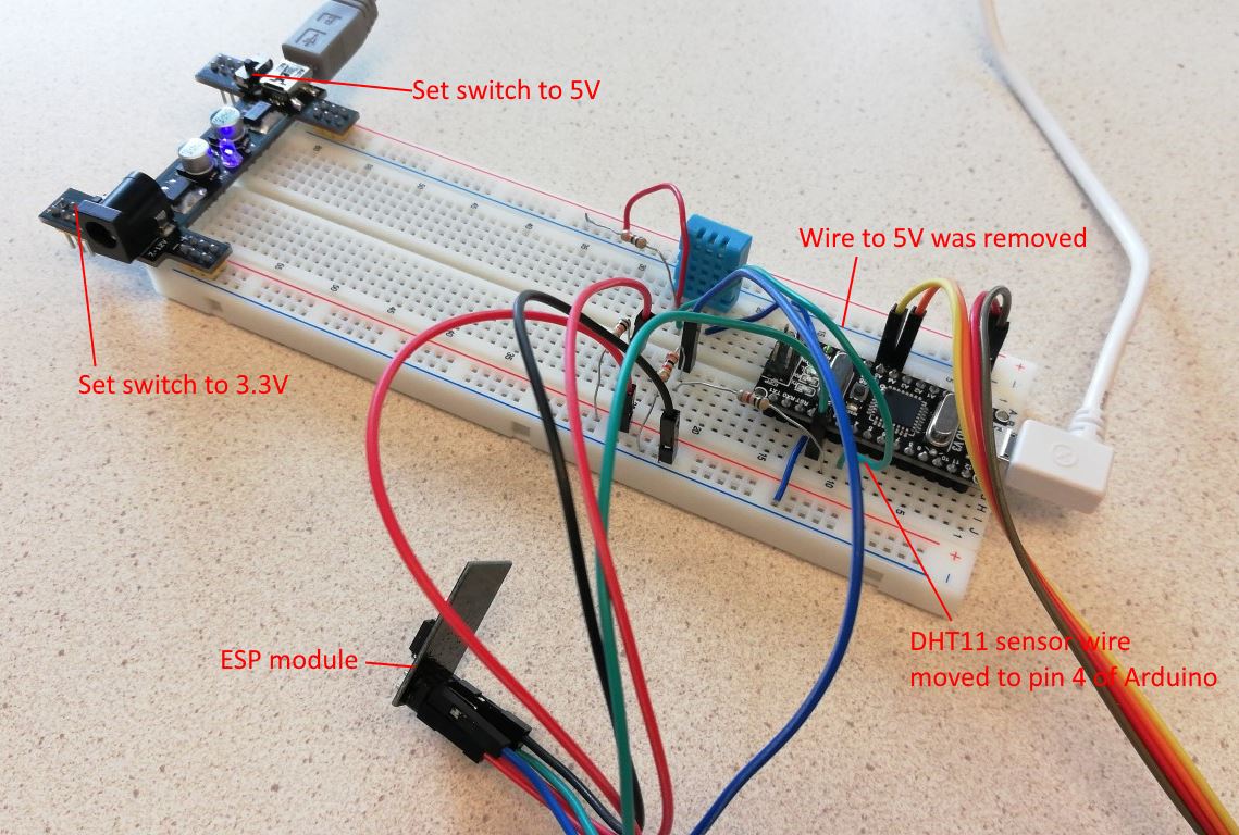
Make sure the ESP8266 module gets 3.3V from the power module. Use the switches on the power module to set one row to 3.3V and the other to 5V (for the temperature sensor). Remove the wire from the Arduino 5V to the power line. Also, move the wire from the sensor pin to pin 4 of the Arduino (it was on pin 2). This will be the result:
Connect to ThingSpeak
ThingSpeak is an online service which you can use to publish data to. We will use it to publish our values for temperature and humidity online.
First, install the ThingSpeak library (Tools > Manage Libraries, search for “thingspeak”).
Go to the thingspeak.com website and signup (register).
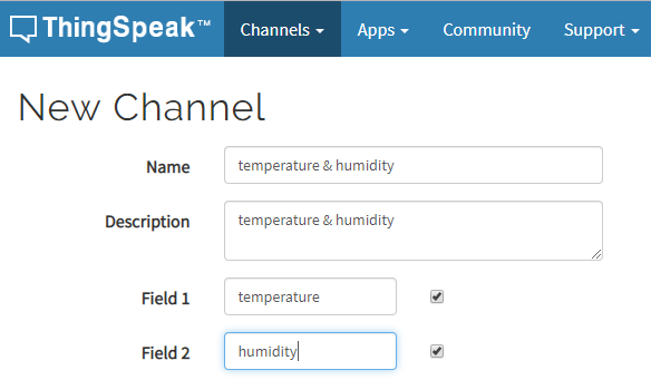
Create a new channel, add two fields “temperature” and “humidity” and save it:
Download the example sketch DHT_Unified_Sensor_thingspeak.ino.
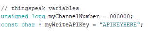
On the ThingSpeak site, go to your channel and click “API keys”, and copy the “Write API Key” and the Channel ID, update the sketch with these values:
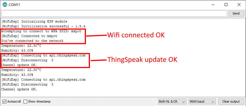
Upload the sketch, make sure it can connect to Wifi (check output in the Serial Monitor). If values get published you will see something like:
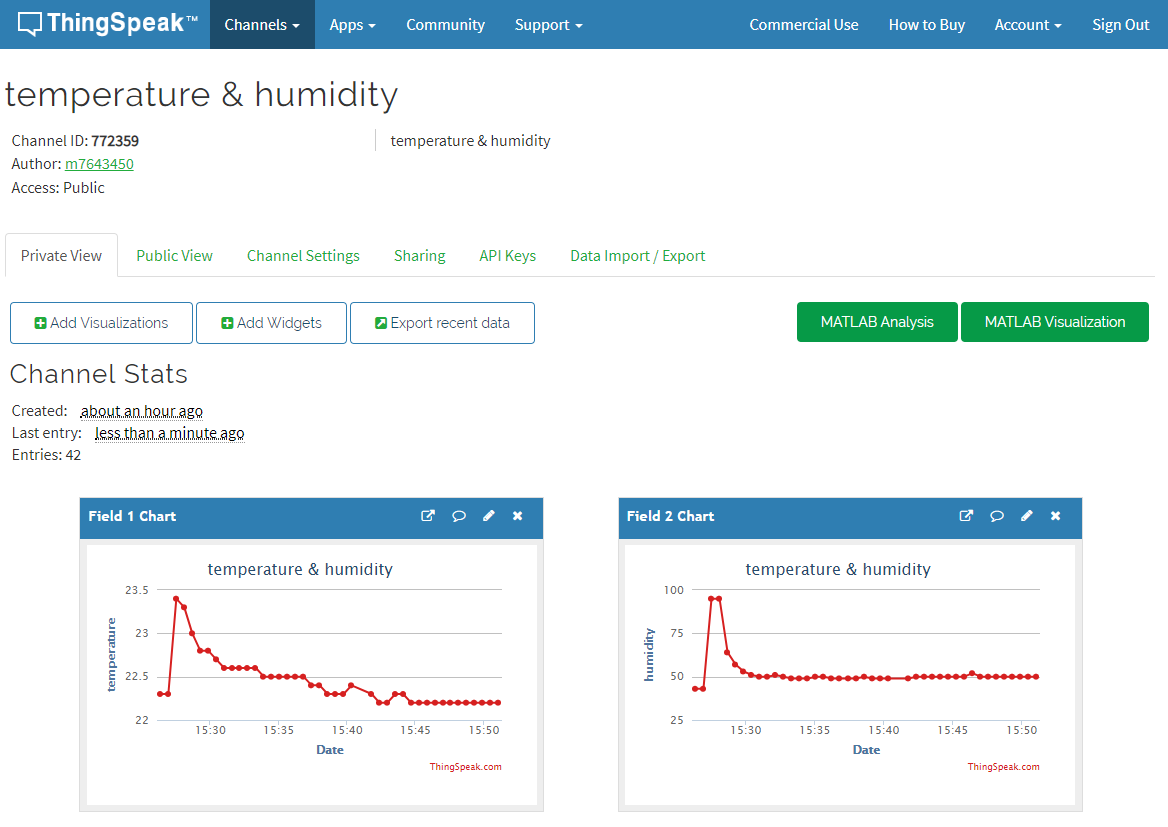
Now check your channel on ThingSpeak and see if the values get updated:
If you want, you may share the channel (make it public): go to Sharing and select “Share channel view with everyone”. You can then also display it in the Java app you will make if you follow my class.