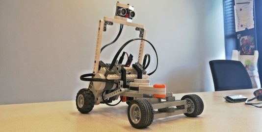
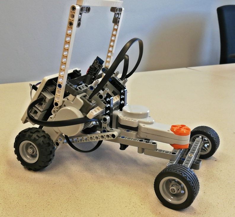
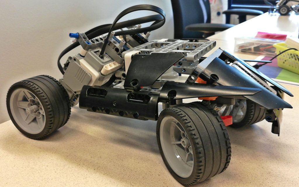
Learn how to build a remote controlled Rover car with Lego Mindstorms, with an Arduino ‘brain’, which can be remote controlled via Bluetooth with a phone.
This guide uses parts from the Steering rover example on nxtprograms.com. It is also inspired by the NXT Dune Buggy.
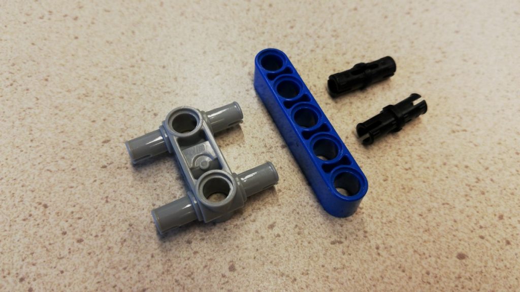
Lego parts shown here might be of different color depending on the type of Lego Mindstorms kit you have. You can click images to enlarge them. If you are doing this as a practical assignment with a group of students, it is advised to do the first 3 steps in separate sub-groups because these can be done independently. So sub-group 1 works on step 1, sub-group 2 on step 2 and sub-group 3 on step 3. Then in step 4 these will be combined.
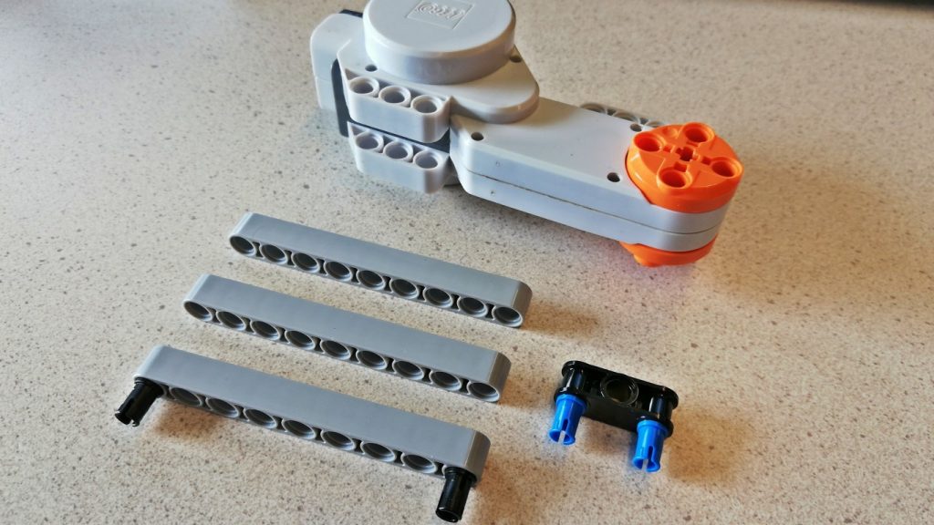
1. Build the front steering mechanism
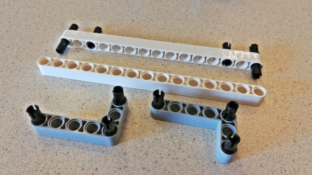
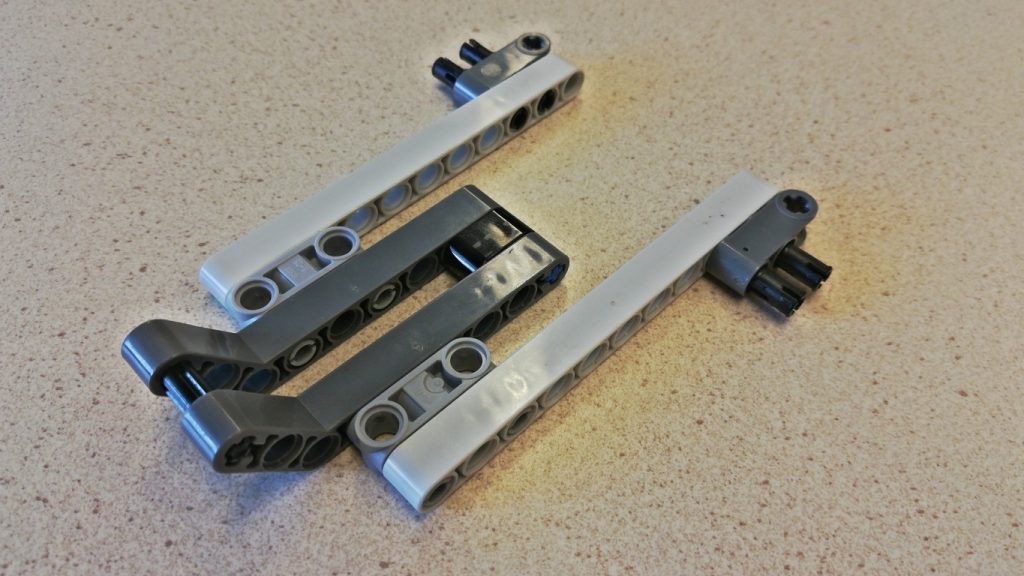
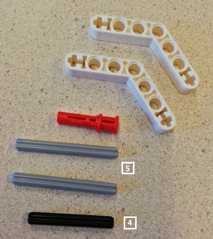
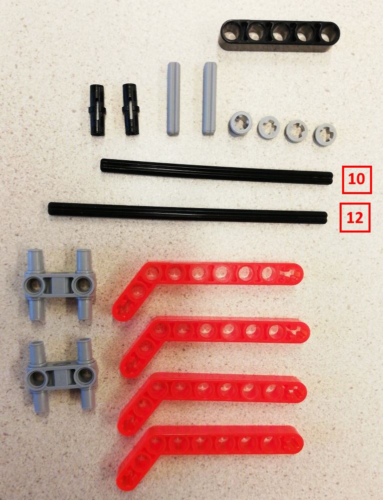
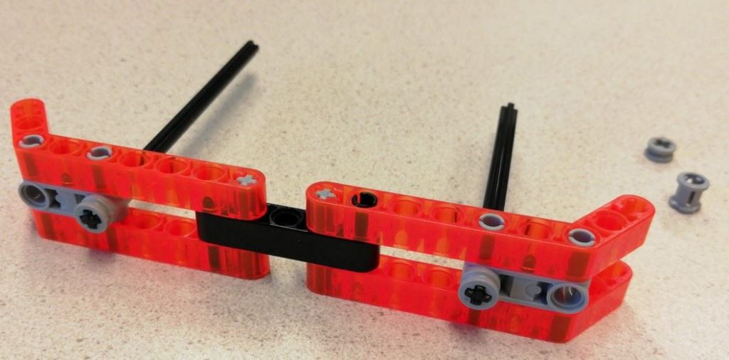
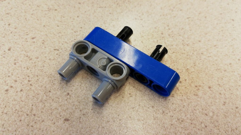
From the image below, you might notice that I used pins of length 13 for the front part (the guide says 11). This does not matter much, 13 fits slightly better with the rear wheel base.
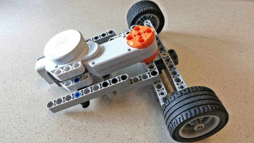
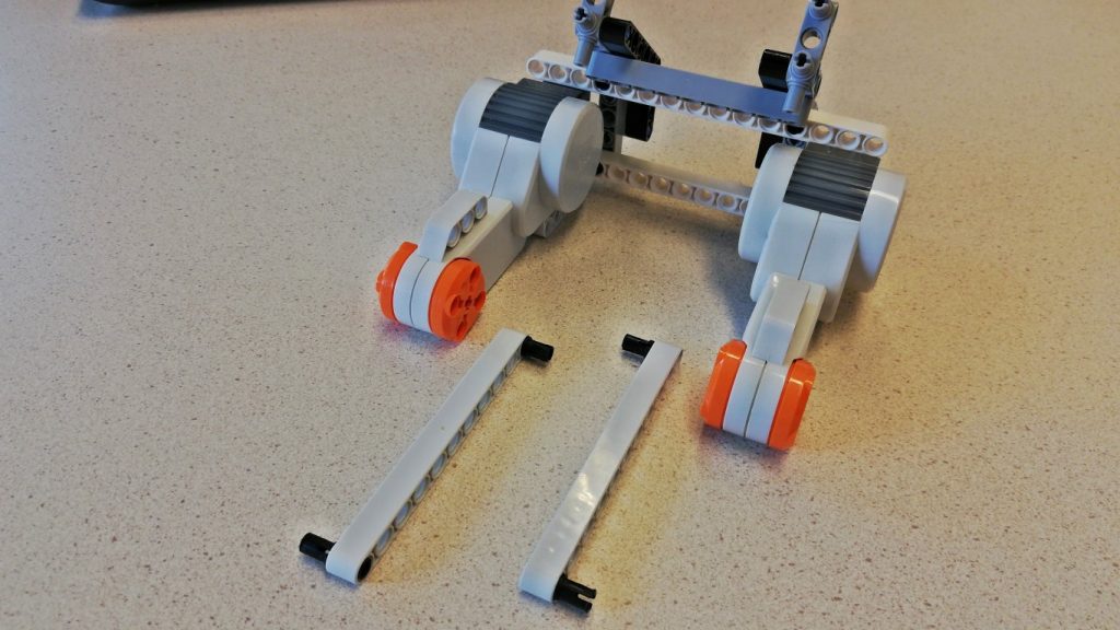
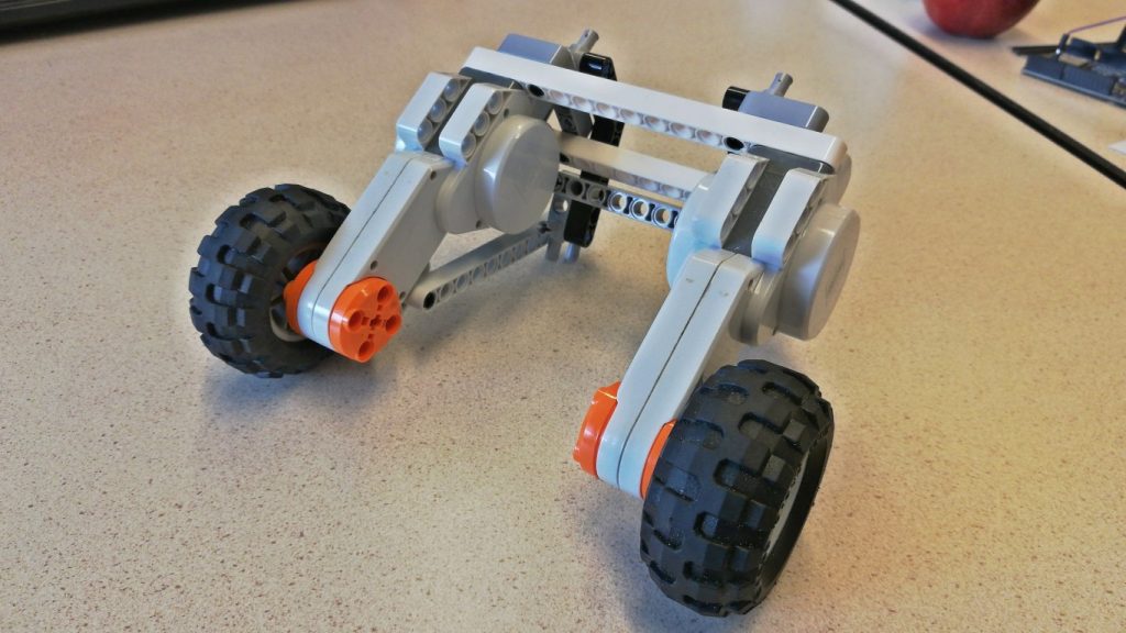
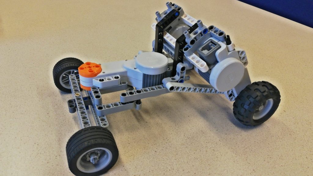
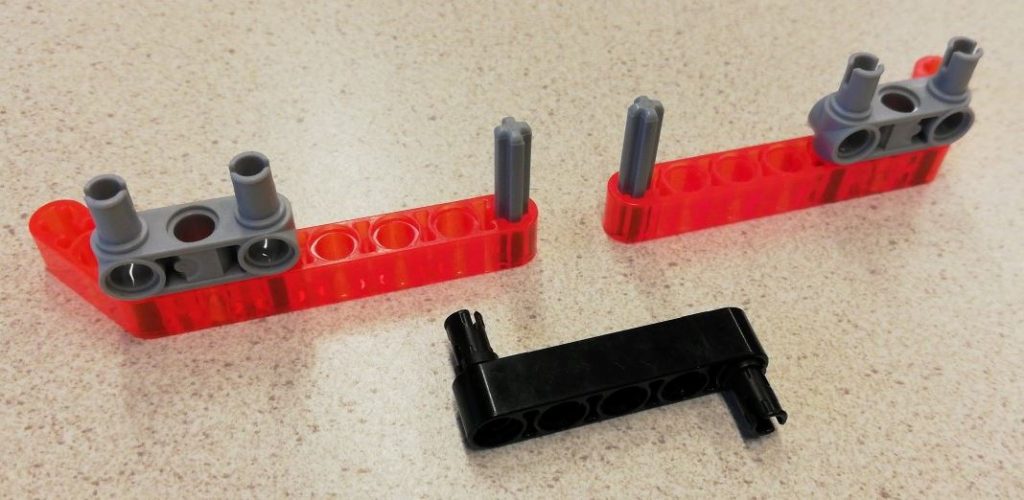
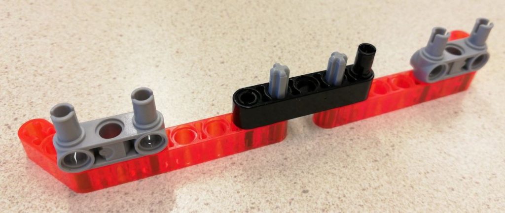
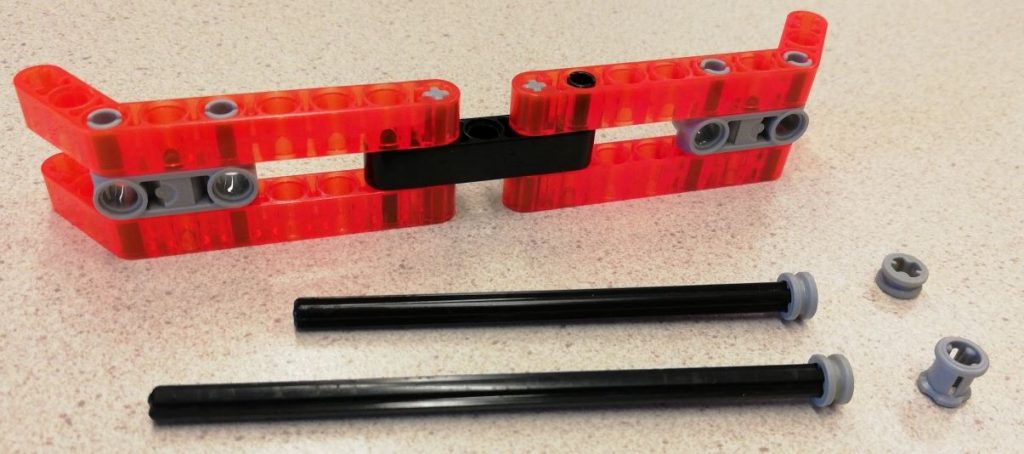
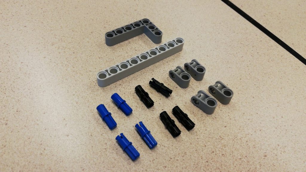
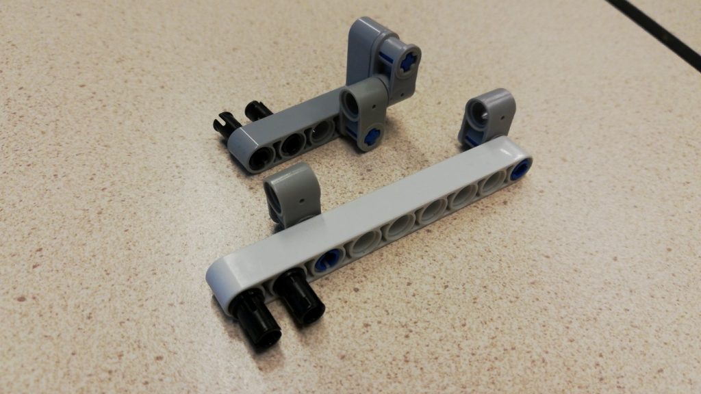
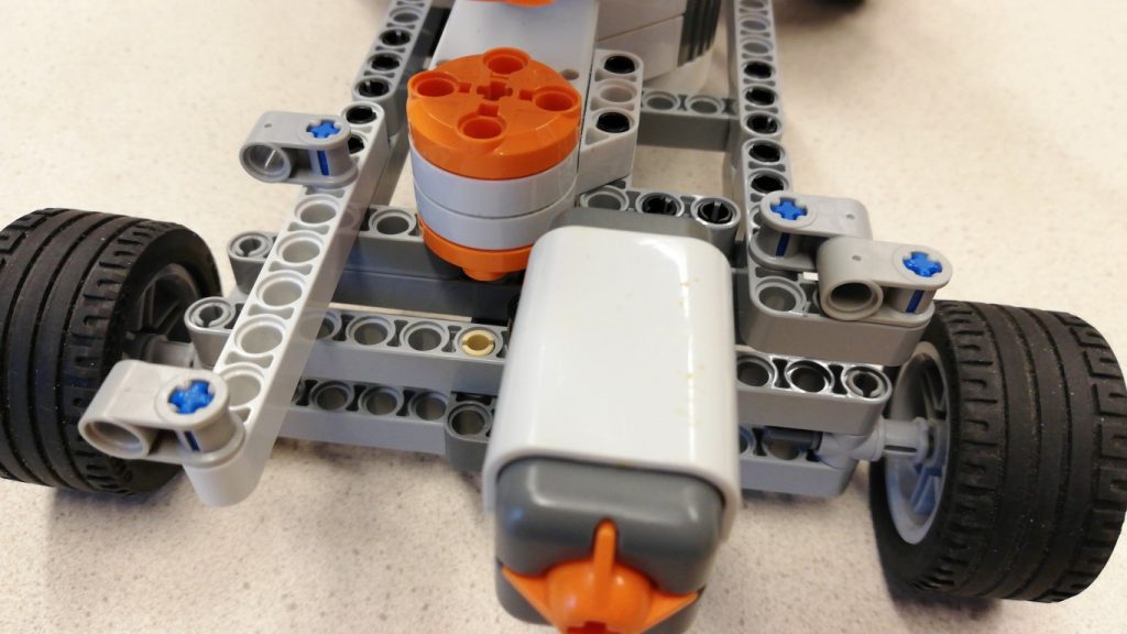
Build the front steering mechanism by following step 4-7 of the steering rover guide. This will result in the front part:

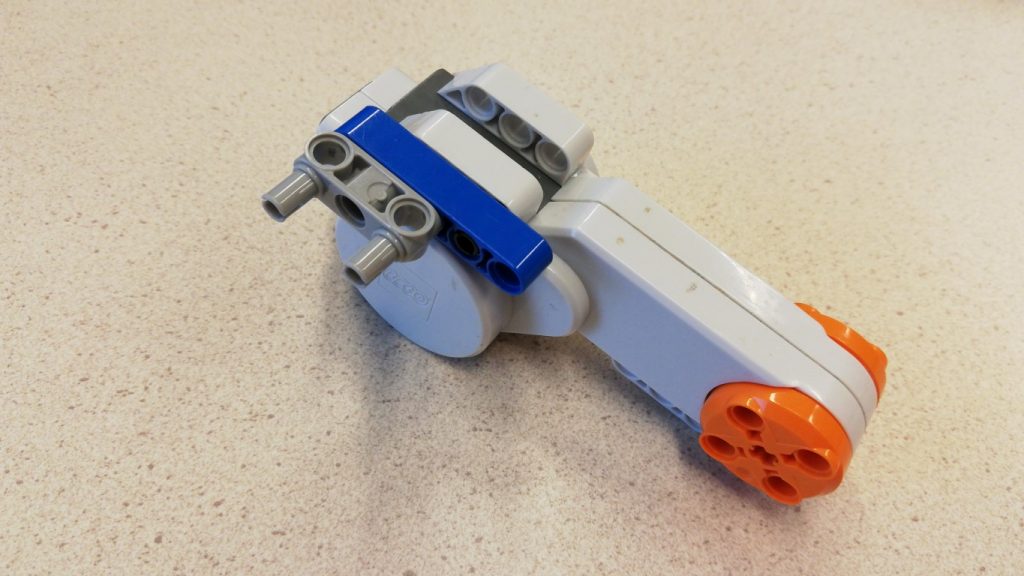
On which we will mount the motor:


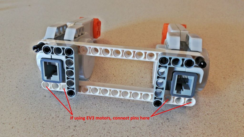
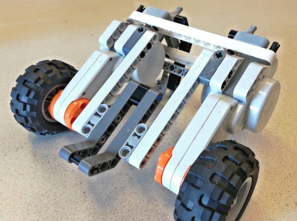
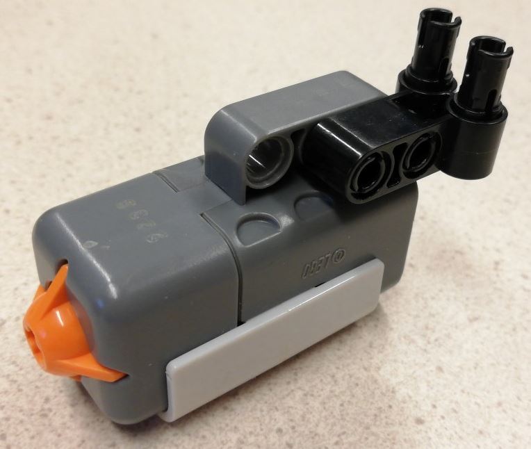
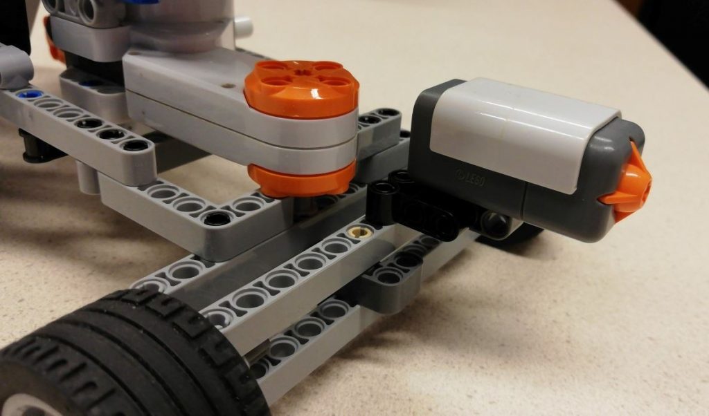
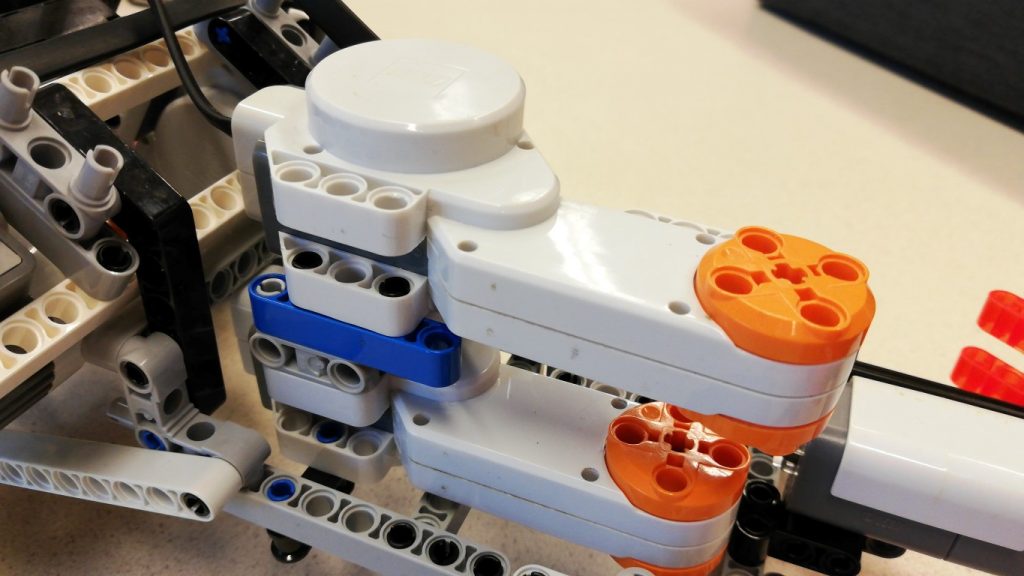
2. Build the rear motor drive
This can be built with either NXT motors or EV3 motors. There are only minor differences.
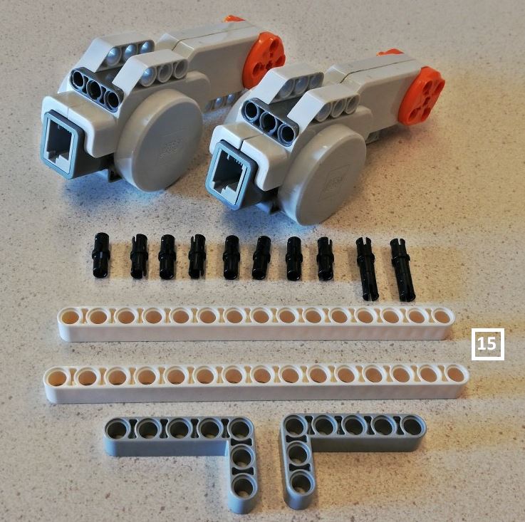
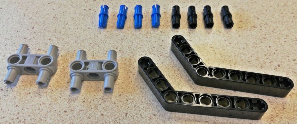
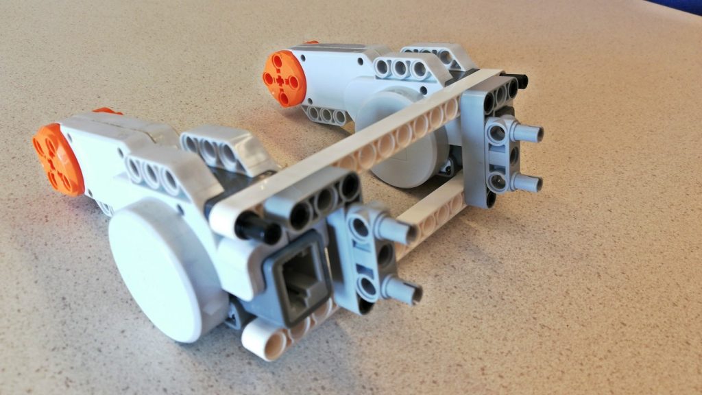
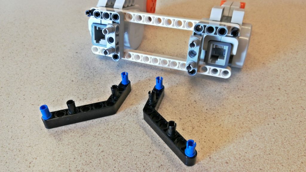
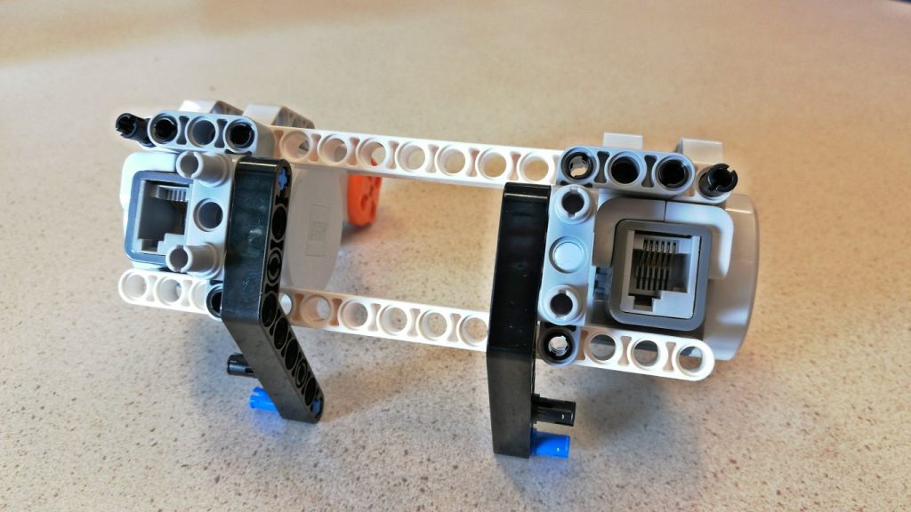
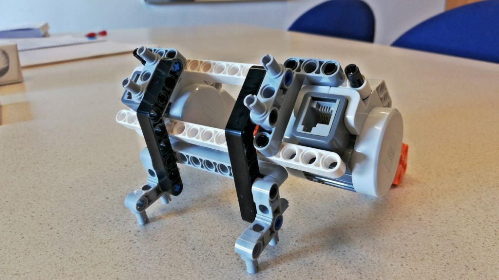

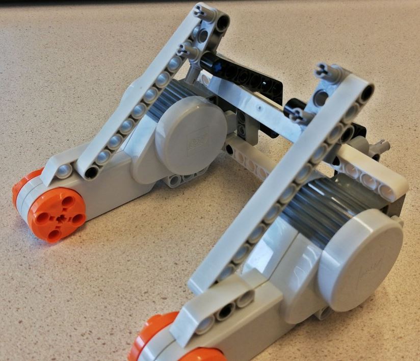
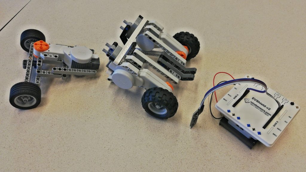
Next, add wheels and the back part (this will hold the EVShield later):


3. Build the EVShield holder and test it
- If you have not installed the Arduino IDE on your computer yet, do this first. Also make sure you installed the set of libraries (check if the folder
Documents\Arduino\Librariescontains the folders “EVShield”, “Dabble”, “NewPing”). - Use this guide to mount EVShield, Arduino Uno and battery holder together, then return to this guide.
- You can download all Arduino sketches used in this guide in a zip-file here: click the green button “Clone or download” and select “Download ZIP”.
- Use an USB cable to connect the Arduino to your computer and upload the test sketch
evshield_test.ino. Press the buttons on the EVShield, do the leds on the shield change colors? Also, start the Serial Monitor and check the output (while pressing the buttons). If everything works fine, proceed. - Follow the steps below to connect the Bluetooth adapter, give it a name, install the Dabble app on your phone and test the EVShield with Dabble:
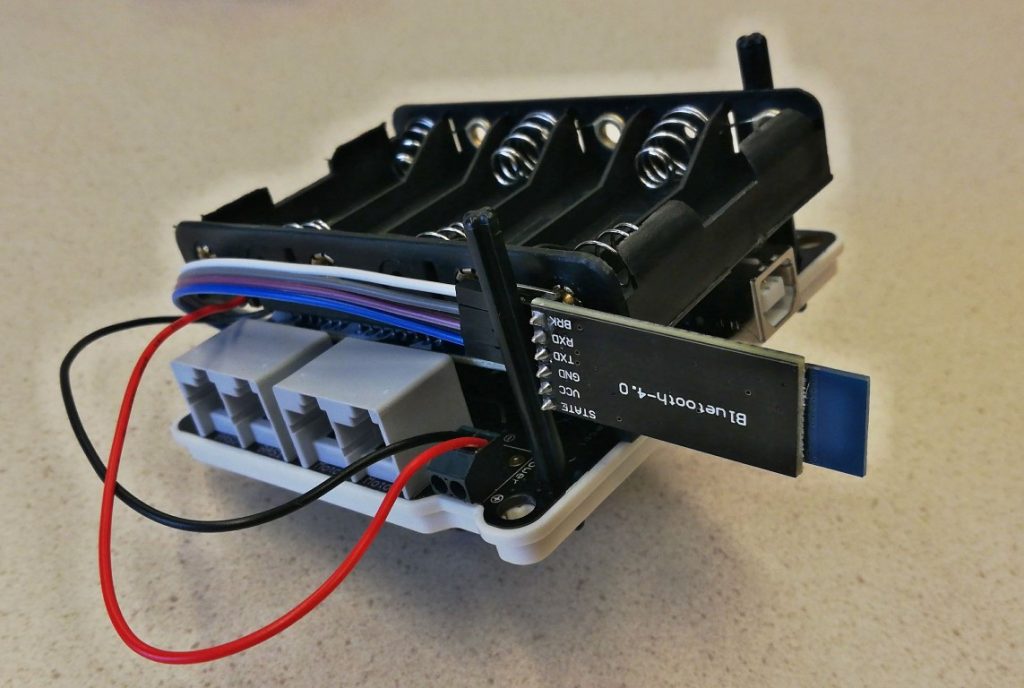
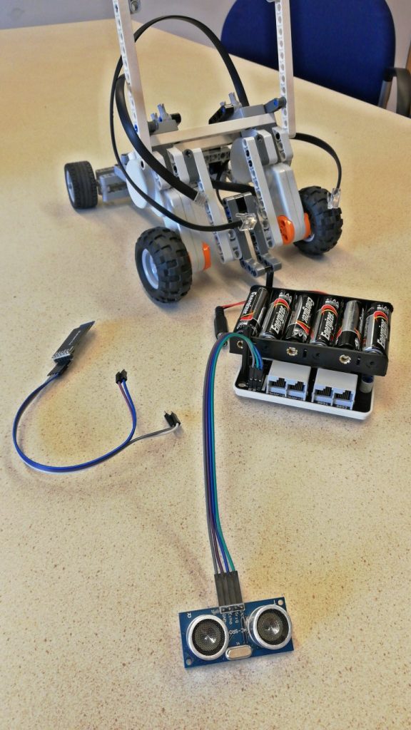
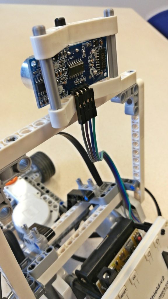
Connect the Bluetooth adapter
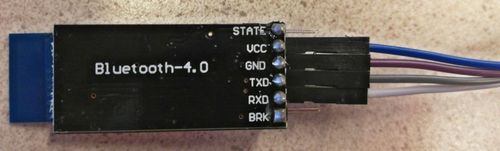
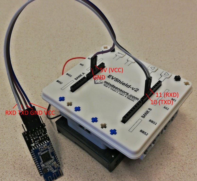
Connect a HM-10 Bluetooth module to the EVShield using 4 male/female jumper wires (the names of the pins are written on the back of the module):
HM-10 TXD - Arduino Pin 10
HM-10 RXD - Arduino Pin 11
HM-10 GND - Arduino GND
HM-10 VCC - Arduino 5V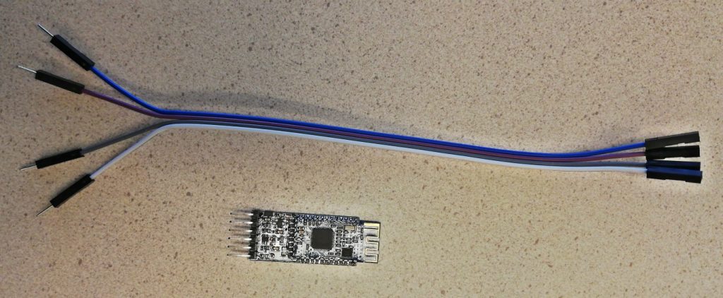
Give the Bluetooth module a unique name
The Bluetooth module needs a unique name to easily select it when connecting to it. Its name can be changed by sending it a AT-command. We will use a sketch which sets up a pass-through connection between module, Arduino and computer to send AT-commands to the Bluetooth module.
Open the Arduino IDE. Load example “SoftwareSerialExample” via File > Examples > SoftwareSerial. In the sketch, find both lines that call the begin() function and change on both lines the baudrate of both to 9600:
Serial.begin(9600); // was 57600

mySerial.begin(9600); // was 4800
Save the sketch. Check the type of Arduino (Tools > Board), this should be Arduino Uno and it’s port (Tools > Port), this should reflect the connected port with (Arduino Uno) behind it. Now click the upload button to compile the code and upload it to the Arduino.
Open the Serial Monitor (Tools > Serial Monitor), set speed to 9600 baud and set Line Ending to “Both NL & CR“:
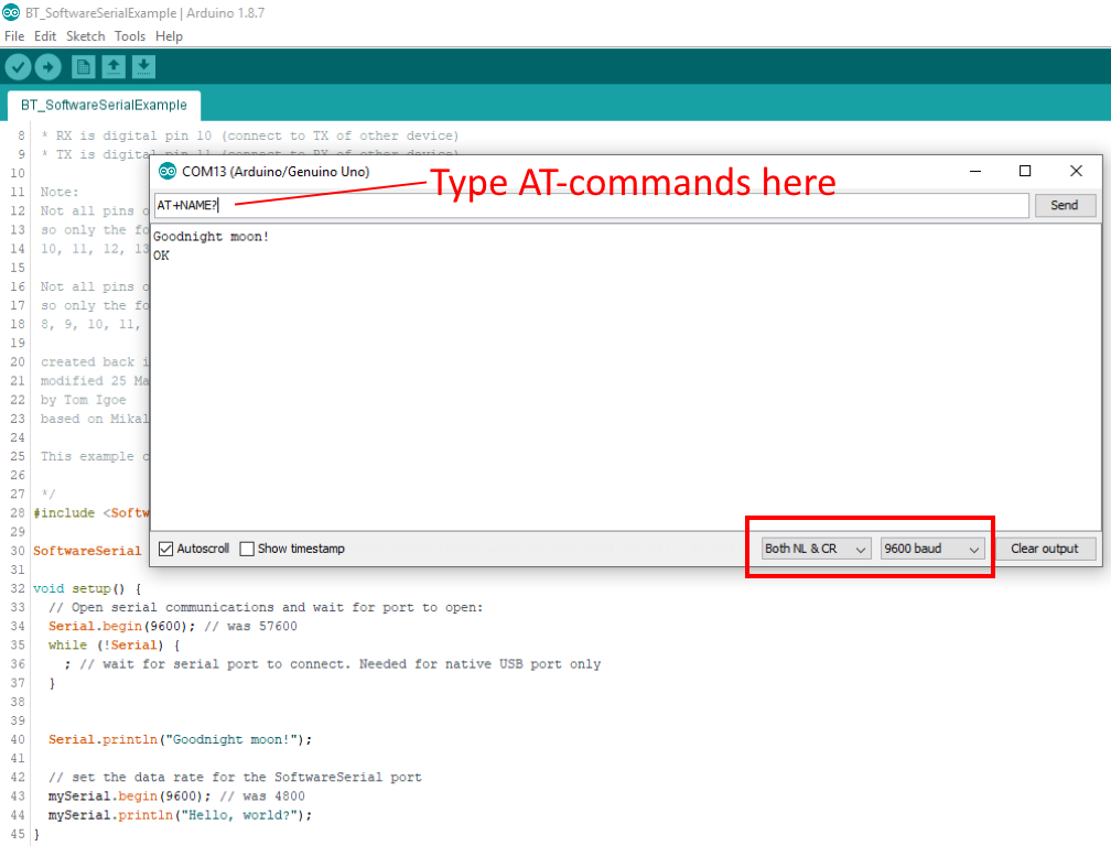
The Bluetooth module uses AT commands to read and write system information, they do not need to be followed by a line break.
If you don’t get a response when you enter a command something may not be connected properly and you’ll need to troubleshoot your module.
When you are connected type:AT – it should respond with OK
You can find your firmware version:AT+VERS? – firmware version
And set your device’s name:AT+NAME? – get current nameAT+NAMEyourname – set the name (12 chars max)
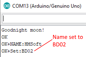
Now using the command AT+NAMEyourname set the device name to something unique, to be able to recognize it easily. For instance, BD (for Bluetoothe Device) followed by your group number. So with the command AT+NAMEBD02 the name of the Bluetooth Device will be set to BD02:
Install Dabble app
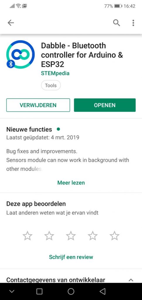
We will use the Dabble app (by STEMpedia) as a remote control for the car. On an Android phone go to the Google Playstore and search for “dabble” or use this link. Install the app “Dabble – Bluetooth controller …”.
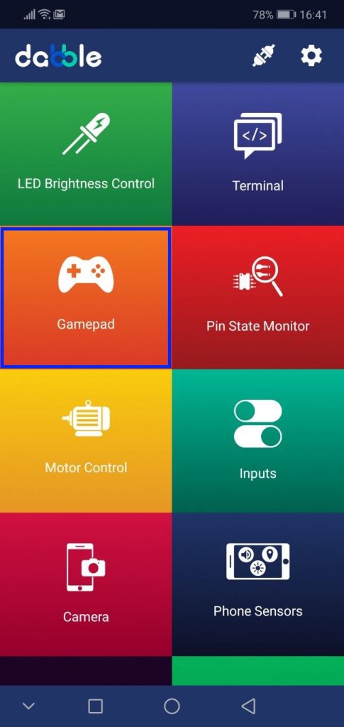
In the main screen, select “Gamepad”. If the mode is asked, select “Digital Mode”.
Test the EVShield with Dabble
- Finding module while connecting: it can take up to a minute for the module to show up in the list.
- Reconnecting: when the connection is lost, after you re-connect, you might have to restart the sketch on the Arduino. This can be done in several ways: hit the reset-button on the EVShield, disconnect and re-connect power, restart the Serial Monitor.
Install the sketch bt_dabble_test.ino and upload it. In the Dabble app, press the connect icon, scroll up/down the list to find and select the name you assigned to the Bluetooth module in the previous step. If the connection succeeds, the led on the Bluetooth module will now be on (if it blinks, it is not connected). Press the buttons of the Gamepad controller: the led on the EVShield should change color for each key and commands show up in the Serial Monitor.
You might notice that not all keys of the Gamepad work. That is because they will not be used for controlling the car.
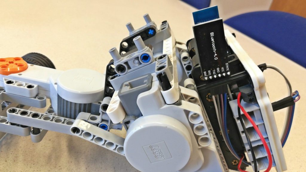
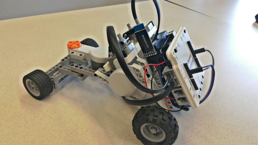
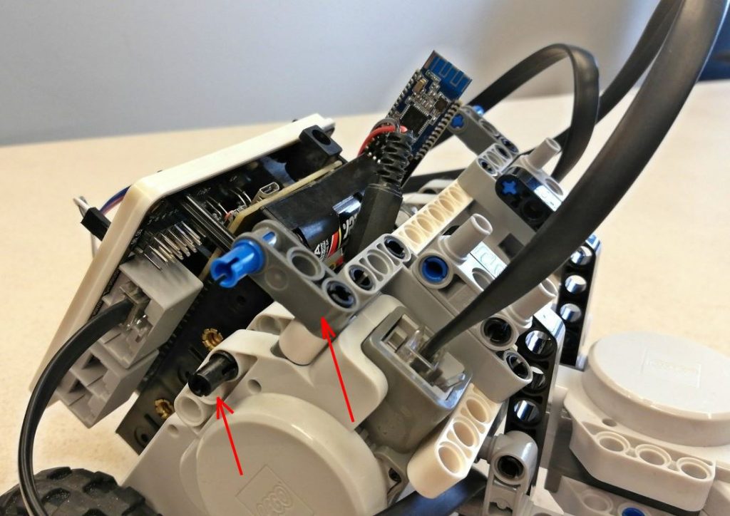
4. Assemble the parts from step 1-3
Assemble the three parts. First remove the grey pieces that hold the battery pack in place and slide the bluetooth module to the side (use the black pin to keep it in place). Connect Lego-wires to the motors: connect the two rear driving motors to M1 and M2 of bank A of the EVShield. Connect the front steering motor to M1 of bank B.
5. Test
Install the sketch rover_bt_dabble.ino and upload it. Disconnect the USB cable. If you did not insert batteries yet, gently remove the EVShield backpack and insert batteries into the battery holder. Start the Dabble app on your phone, connect and use the Gamepad controller to drive the car.
Tip: keep tests running on batteries short, as driving motors will drain the batteries quickly. You can also do basic testing with USB cable connected (and batteries removed/disconnected).
Check if going forward and backward and steering works properly. If not, check the hint in the comments of the Arduino sketch, eg. to fix the direction in which the car moves. Study the code of the sketch, can you figure out which keys of the gamepad control which functions of the car? Hint: study the loop() function.
To optimize steering, you can adjust the values of the variables car_rear_track and car_wheelbase (under // car dimension related). Measure the car’s rear track and car’s wheelbase and assign the values (in mm) to these variables (ruler and tape measure are available from the teacher):
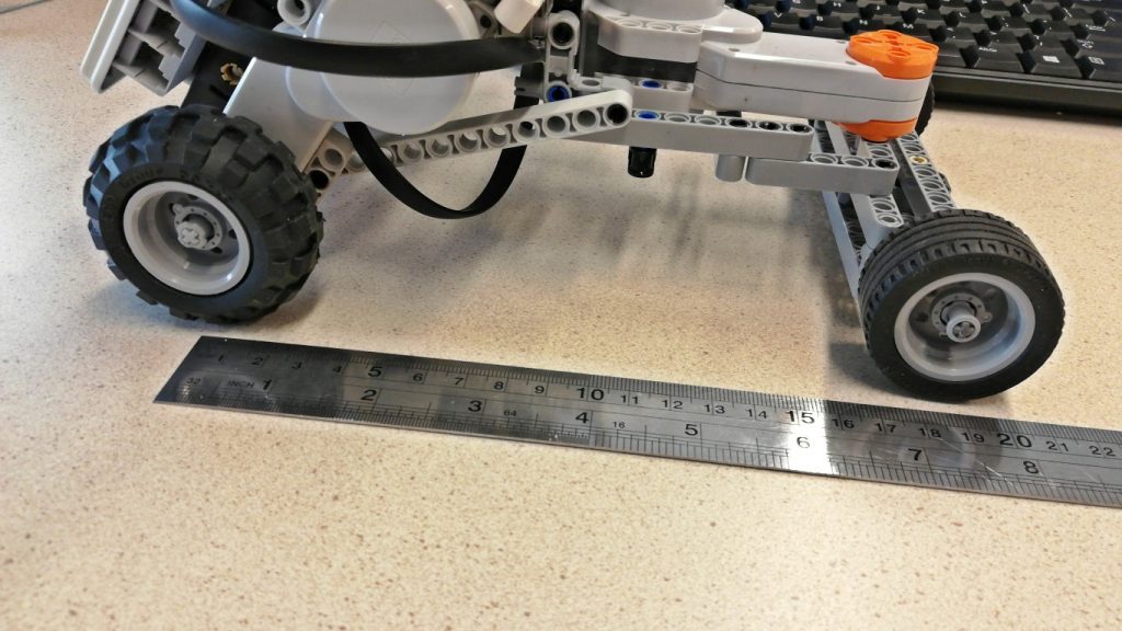
Wheel base 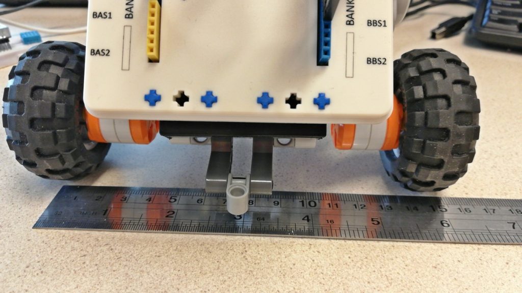
Rear track width
6. Add top bar with Ultrasonic sensor
Add top bar to car
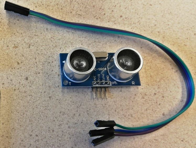
Connect Ultrasonic sensor to EVShield
Get 4 female-female jumper wires and the Ultrasonic sensor. Connect the wires to the servo connector at the back of the EVShield. To do this, temporary remove all wires from the EVShield, to easily access the pins of the servo header. Tip: take a photo of the wires of the Bluetooth connector, so you can quickly re-attach them later.
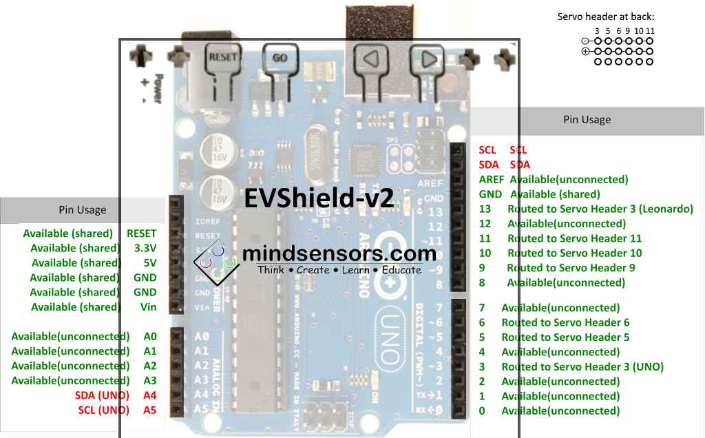
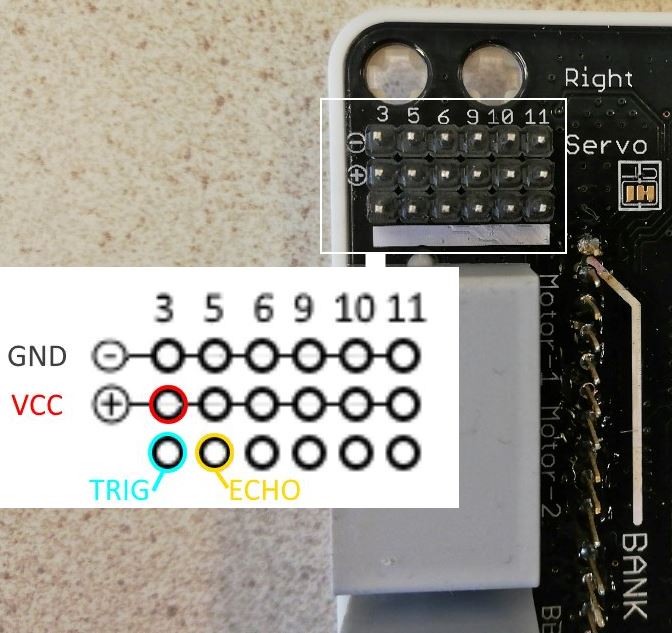
We will connect the wires to the servo-headers of the shield which are at the back (the bottom). The servo-headers have one row of pins connected to pins 3, 5, 6, 9 10, and 11 of the Arduino, and a row connected to GND (-) and a row connected to VCC (+), which gets 5V if a power source is connected directly to the shield (eg. a battery pack). Power via USB cable is not sufficient (the output will not be 5V!). Connect the ultrasonic sensor using female-female jumper cables to the servo pins as indicated:
Power the EVShield with batteries and connect the Arduino with the USB cable to your computer. Now upload this test sketch ultrasonic_sensor_HC-SR04_newping.ino to see if the sensor works. You should see the distance measured in the Serial Monitor. Remove one battery from the pack to save power.
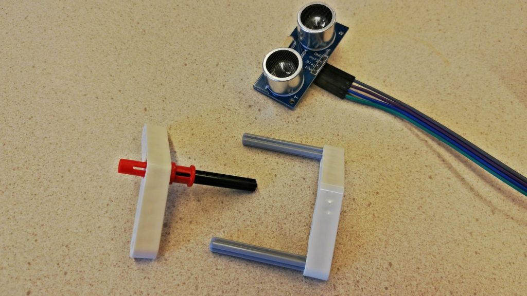
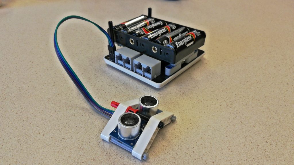
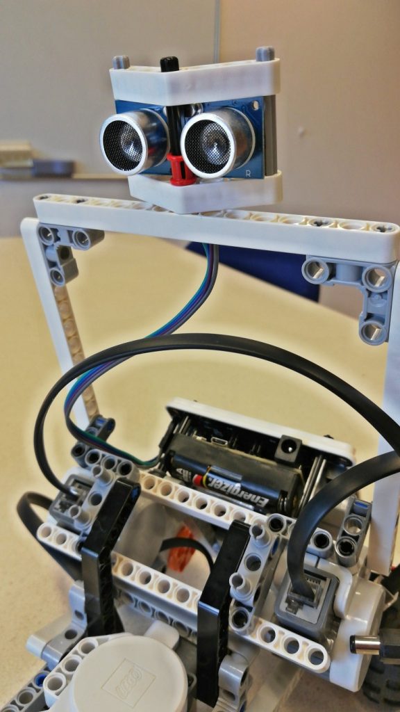
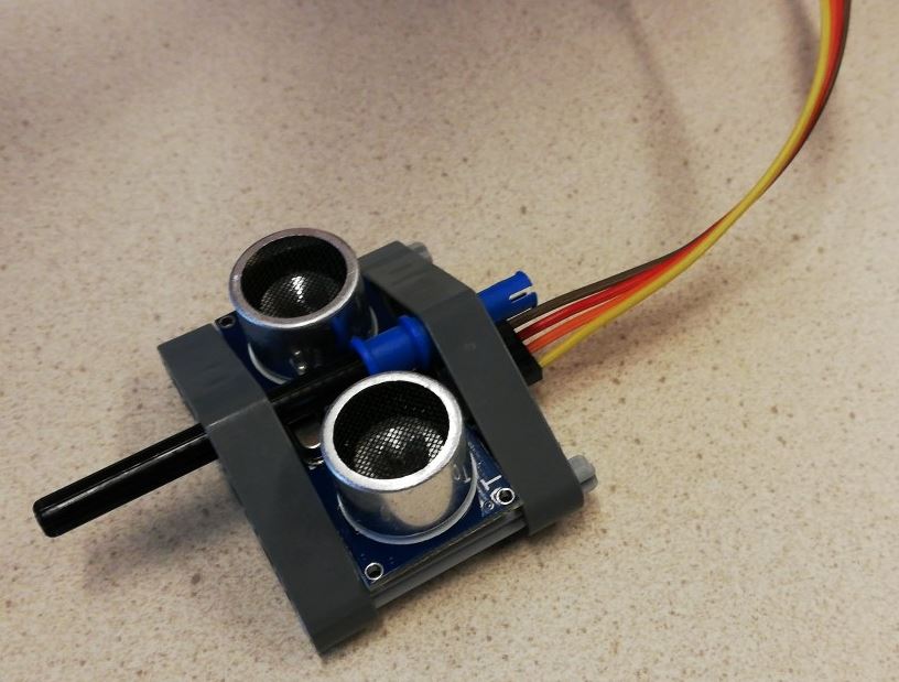
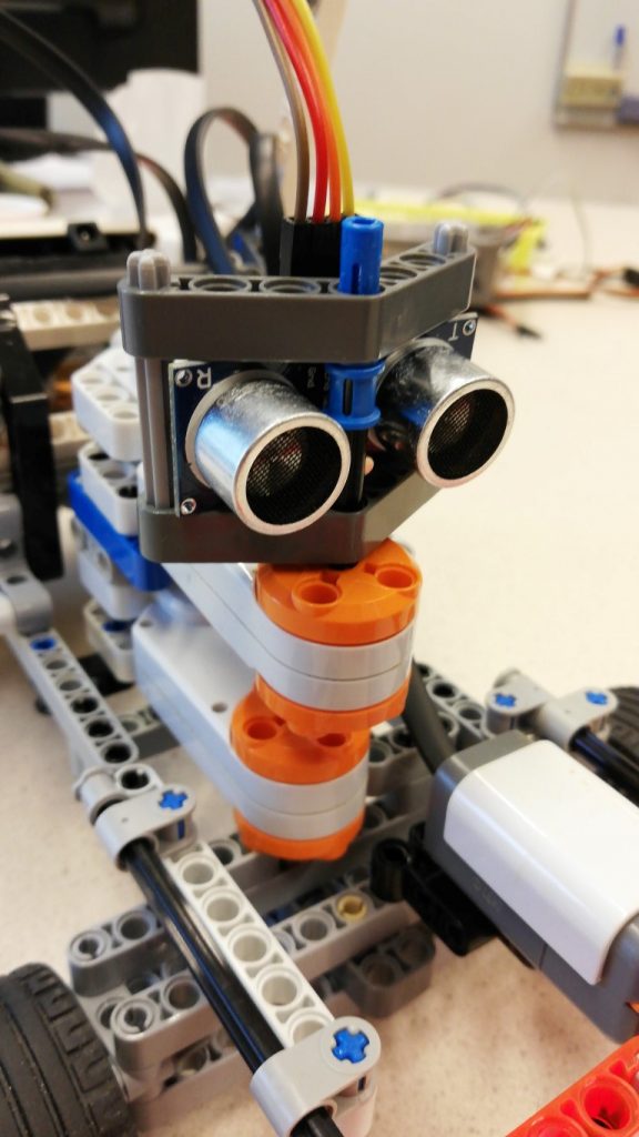
Make enclosure for Ultrasonic sensor
Make the enclosure for the Ultrasonic sensor and attach it to the top bar:
Test: stop when obstacle detected
Re-insert the battery. Run this sketch rover_bt_dabble_ultrasonic.ino to test the car: does it stop when moving forward and distance < 30 cm?
Can you find the code which checks this condition?
7. Improve the car
If you are doing a practical session and you have some time left, here are some things you can improve.
Mechanics: Like the dune buggy, you could add seats and bars to make it look more like a buggy. An example:
Let’s make it smarter. You could add:
A ‘horn’ (buzzer) which warns objects that are too close (but not that close that it stops, eg. distance < 100 cm).
A color sensor which makes the car make sounds as the car drives over colored tiles, or make it follow a colored line on the floor.
A (joystick) controller to manually operate it (that’s actually -less smart- ;-). You can borrow the joystick from your teacher.
A display, which for instance displays status-information and speed from the car.
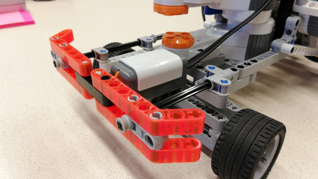
Add a bumper
A way to make the car ‘behave’ better in situations with obstacles and without remote (or proper) control, is to add a bumper. To detect whether it bumped into something, we use a touch sensor behind the bumper. The way the shown bumper is made is just one of many possible ways this can be done.
Because of the way the front steering mechanism is build, the touch sensor has to be mounted slightly off-center:
Use the images below to build and attach the bumper. First, build the bumper:
Create a fixture and mount the bumper:
Add a rotating ultrasonic sensor
In situations with an obstacle in front of the car, a scan can be done with the ultrasonic sensor to find a direction without obstacles. For this, we can mount an ultrasonic sensor onto a motor. The holder for the ultrasonic sensor was altered slightly: a longer axle was inserted and the sensor was turned upside down.
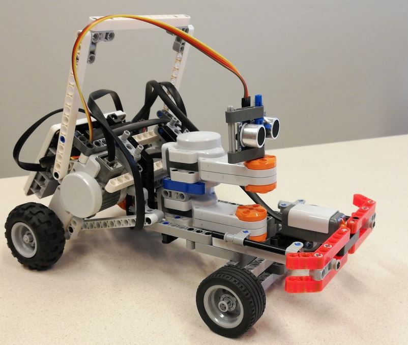
The resulting version of the Rover car with bumper and rotating ultrasonic sensor:
Reference
Arduino libraries used: