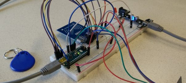
We are going to build a circuit that is connected to an app build with Blynk. For this we connect an Arduino to an ESP8266 module and connect it through Wifi (step 1). This example uses an Arduino Nano, of course you may use an other type of Arduino, eg. the Uno. In the second step we add some electronics to the circuit and show you how to control that via the Blynk app.
This guide assumes you already have some basic knowledge of Arduino and electronics and already did the “Getting started with Blynk” tutorial (for step2).
Step 1: Connect and setup the ESP8266 module
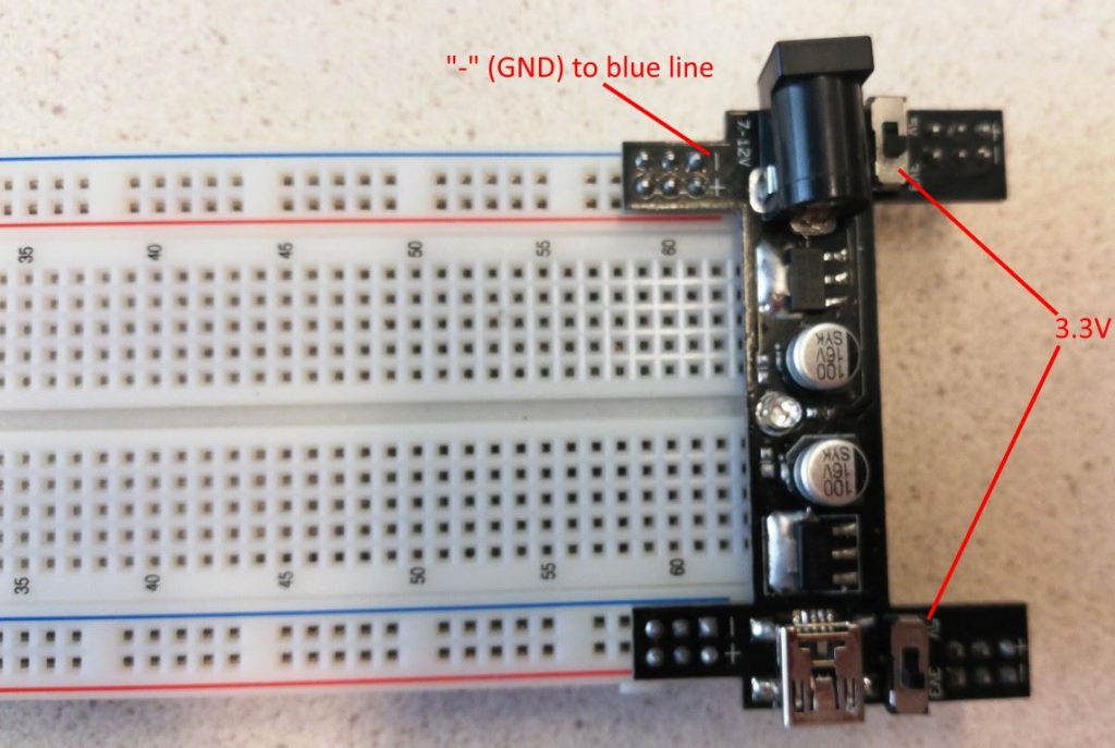
Attach a breadboard power module to a breadboard. Make sure the – (GND) connects to the blue lines and + to the red lines. Set both switches on the power module to 3.3V.
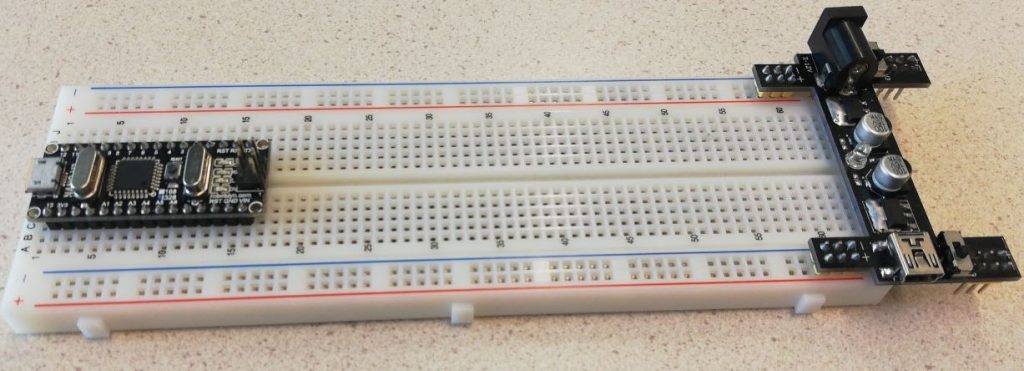
Insert an Arduino Nano on the other end of the breadboard:
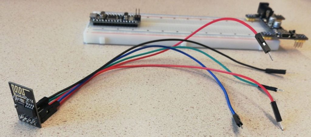
Connect wires to the ESP8266 (only to the pins we will actually use, the the schematic below):
Now connect everything according to the scheme:
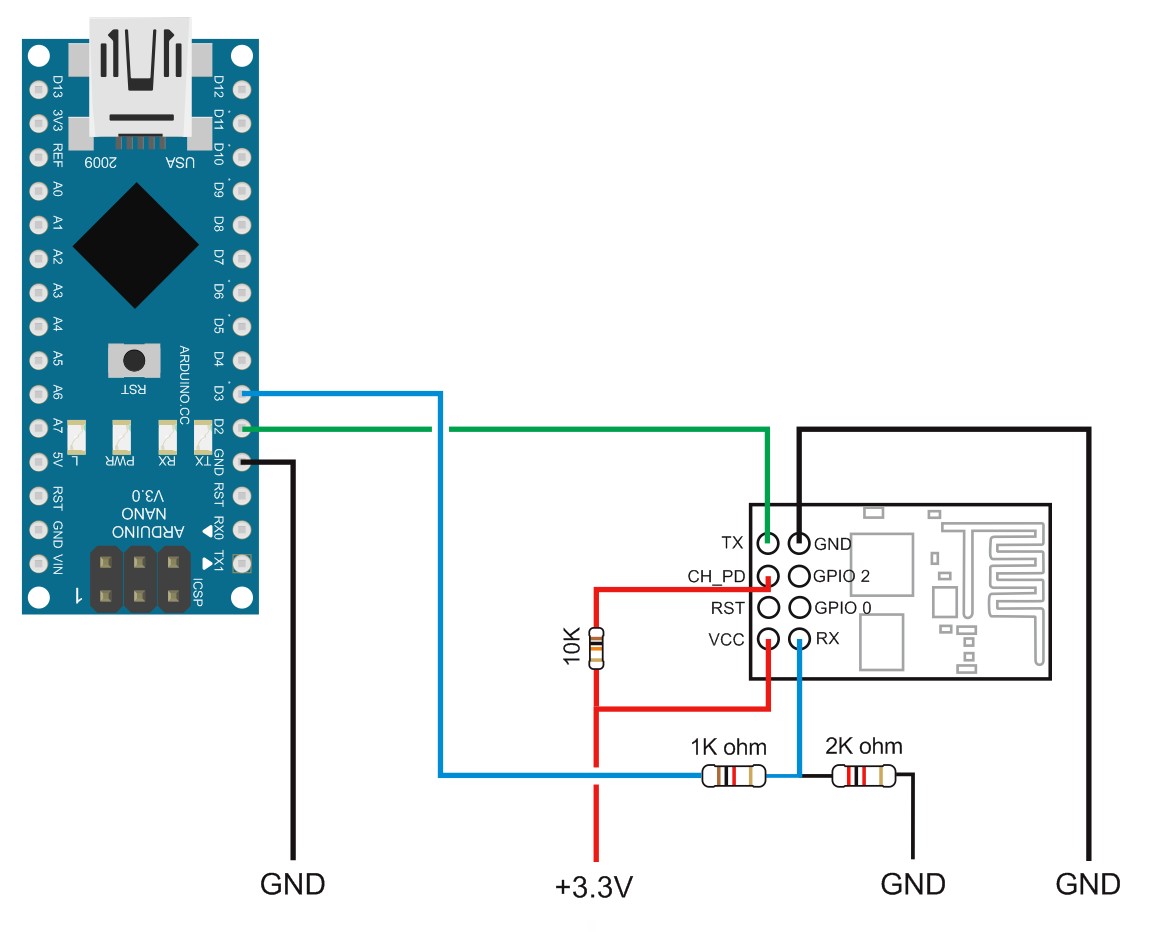
Do not forget to add a GND wire (from Arduino GND to the blue power line on the breadboard).
TX from ESP8266 is connected to D2, RX to D3 of the Arduino (via 1K resistor). Beware that the 3.3V from the Arduino is usually not sufficient* to power the ESP8266 module. This is why we use a separate 3.3V power source: the breadboard power connector.
Take special care: for this type of breadboard power connector, never connect both wings to power sources! (USB power and a power adapter) You risk blowing up something, in the worst case your laptop!
Connect a USB cable to the breadboard power module and make sure the lights on the breadboard power module and the ESP8266 module turn on:
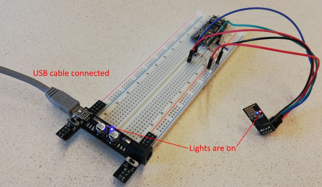
Now connect a second USB cable to the Arduino Nano.
Test and configure the module
Download the example sketch first_ESP8266_v2.ino
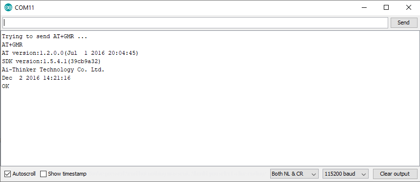
This example can initialize and test a new module. Read comments in code for details. It is based on this example. The sketch should show something like this in the Serial Monitor:
If it does not work, read the comments in the sketch carfully. Troubleshooting tips:
- Check if the speed of the Serial Monitor matches the speed set in the sketch.
- Disconnect the USB cable from the breadboard power module and connect it again.
- The speed of the ESP8266 might be different from the speed set for
EspSerial.begin(9600);in the sketch. Adjust the speed (try the values mentioned in the comment behind that code) and upload the sketch.
Now you must reset the device, set its speed to 9600 baud and configure it as a Wifi Client (Station mode) by sending it the commands as described below. You communicate with the module by sending it AT-commands through the Serial Monitor. The comments at the top of the sketch contain instructions and examples how to do this. If it does not work, check out the “ESP8266 troubleshooting” section at the bottom of this article.
Using the Serial Monitor, send this command to reset the module:
AT+RST
If you have modified the speed (eg. to 57600, 76800 or 115200), reset it to 9600 with this command:
AT+UART_DEF=9600,8,1,0,0
After you have set the speed, find the line in the sketch in setup() which sets the speed again and set it back to 9600. Upload the sketch again.
Now set the module to function as a Wifi client:
AT+CWMODE=1
The last setting is to turn off command echoing:
ATE0

Connect to Wifi
After you have configured the module as a Wifi client, it can connect to a Wifi network.
Download the second sketch first_esp8266_connect.ino Open it in the Arduino IDE, change the password (variable ‘pass’) and if necessary the ssid. If you are doing a practical session, the password should be available from the teacher. Upload the sketch. The module should connect to the Wifi network (eg. “mspot”) and print details about the connection in the Serial Monitor. If it does not work, check out the “ESP8266 troubleshooting” section at the bottom of this article.
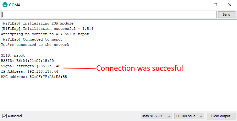
Unfortunately, the ESP8266 can not connect to the EDUROAM network we use at the university. That’s why I usually bring a Wireless Router to my workshops, which uses the SSID “mspot”. As an alternative you can turn your phone or laptop into a mobile hotspot.
Step 2: Add a LED and control it with Blynk
If you did the “Getting started with Blynk” tutorial first you still have a LED connected to your Arduino. If not, connect a LED.
In the Arduino IDE load the “ESP8266_Shield” example via File > Examples > Blynk > Boards_WiFi . And change settings in red:
// You should get Auth Token in the Blynk App.

// Go to the Project Settings (nut icon).

char auth[] = "********";

// Your WiFi credentials.

// Set password to "" for open networks.

char ssid[] = "mspot";

char pass[] = "********";

// Hardware Serial on Mega, Leonardo, Micro...

//#define EspSerial Serial1

// or Software Serial on Uno, Nano...

#include <SoftwareSerial.h>

SoftwareSerial EspSerial(2, 3); // RX, TX

// Your ESP8266 baud rate: (was 115200)

#define ESP8266_BAUD 9600
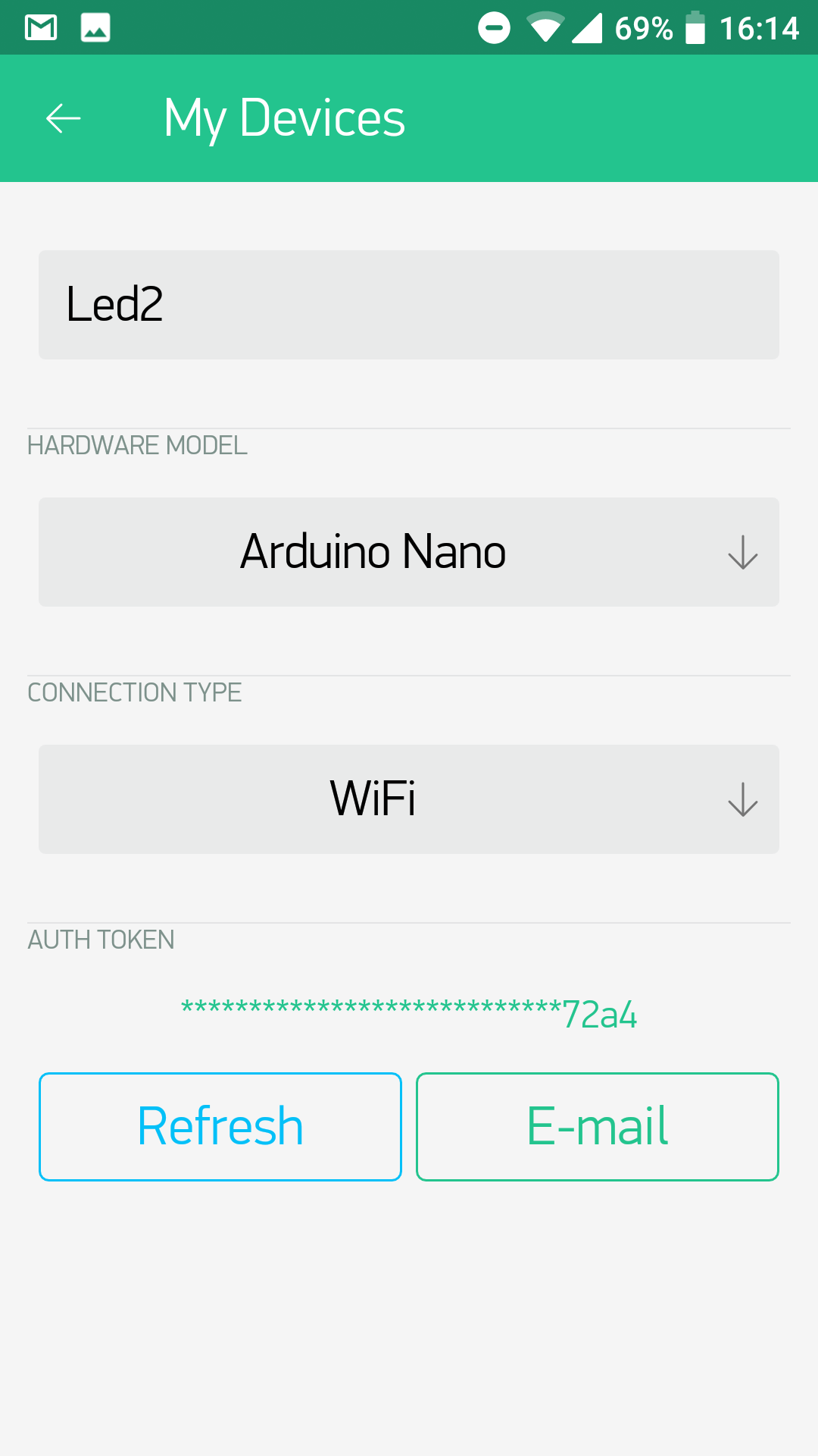
The auth variable should contain the Auth Token from the Blynk App (you can get it from the project settings in the app).
Run the sketch.
In the Blynk App, change the project settings to reflect the new way we connect to the Blynk cloud, via Wifi:
If you have the example from the “Getting started with Blynk” tutorial on your phone, you should now be able to control the LED from your phone.
Final step: add RFID module and identify a person (in the App)
Add the RFID module (step-by-step guide here). Add the necessary code to the Arduino Sketch. You may use this complete example: first_esp8266_rfid.ino
The display widget ‘lcd’ is used to display the RFID code in a display widget in the Blynk App (which is connected to virtual pin V1). Add a LCD widget to the userinterface:

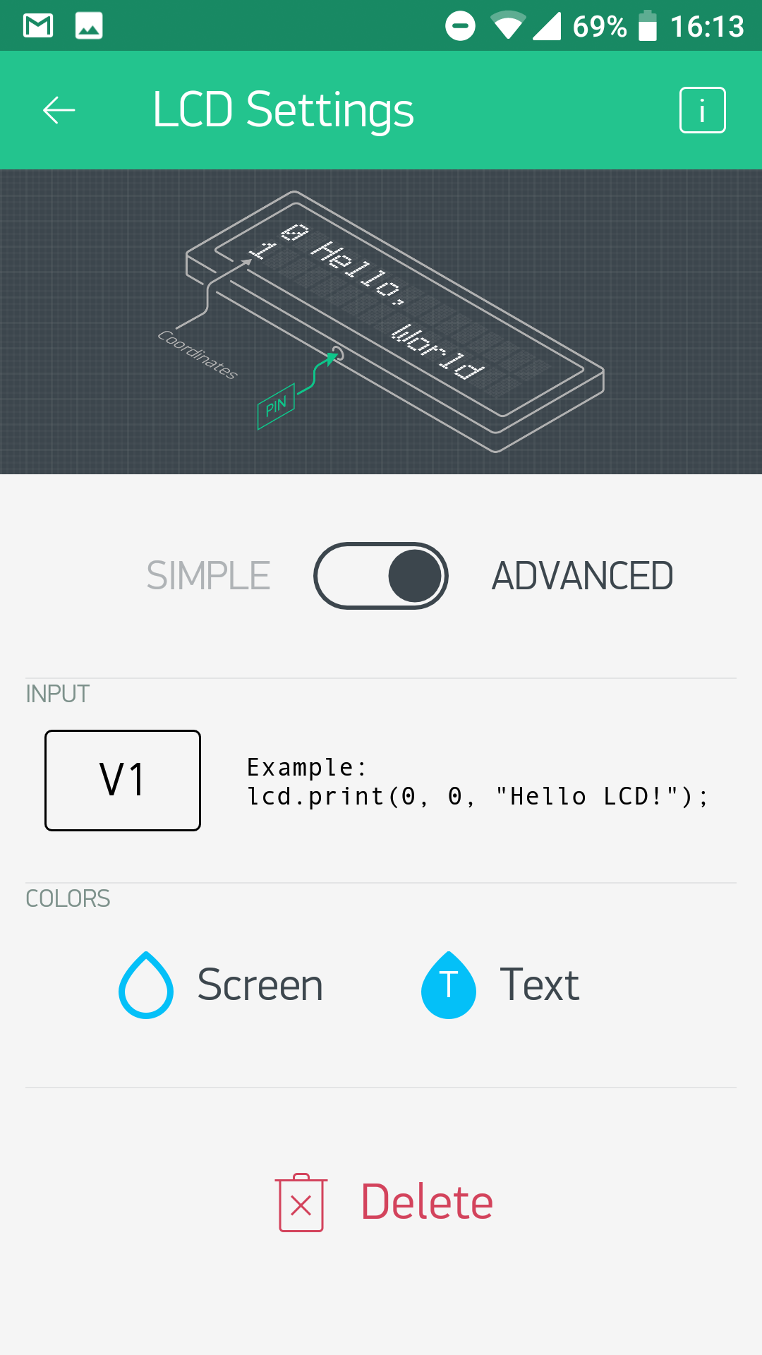
In the Arduino sketch, when an RFID is scanned, its ID will be sent to the display (lcd in the code) like this:
lcd.print(0,0, rfidUid);
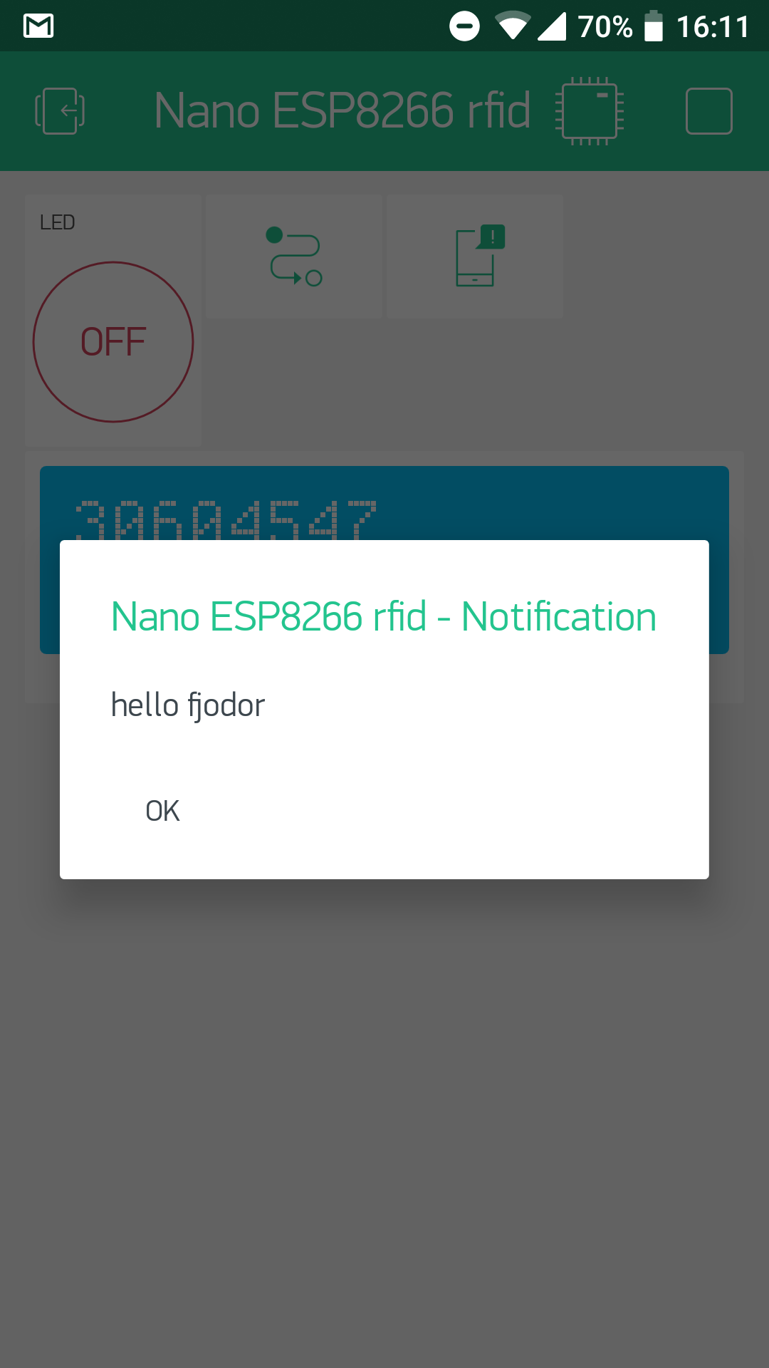
Test the App, it should display the ID if you scan a card.
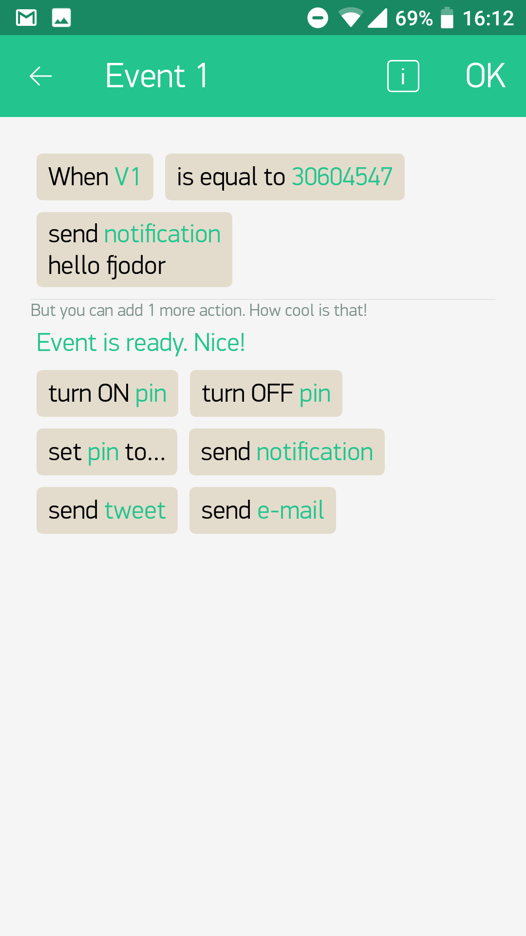
As a last example, we will add a notification to the App, which will display a notification if the card scanned is from a specific person. In the Blynk App, add an Eventor and a Notification widget. The Eventor can respond to events (if this … then …). In the Arduino sketch, when an RFID is scanned, it will be sent to a virtual pin V1 like this:
Blynk.virtualWrite(V1, rfidUid);
When this event occurs, the Eventor widget in the App can respond to it:
Use the ESP8266 standalone
For more compact circuits, you can also use the Wifi module without an Arduino, like this project “ESP8266 Temperature / Humidity Webserver”.
ESP8266 troubleshooting
If the ESP module is unable to connect or appears unresponsive, double-check the wiring. Are all wires connected according to the schematic in step 1 of this article?
As a next step, you can reset the module: connect a wire to the RST pin of the module and make sure the module is powered (the red LED on the module should be on). Then, for 2 seconds, connect the wire to the GND. After that, connect it for 2 seconds to the VCC (3.3V). Remove the wire and try again.