
This guide explains how to build the Lego Mindstorms model “Spike”, powered by an Arduino and an EVShield. The original version of the Spike is powered by a Lego NXT.
Requirements
- EVShield, Arduino Uno, Battery holder (+6 AA batteries)
- Lego Mindstorms kit (can be either NXT or EV3)
Introduction
To make a sturdy, compact solution which allows access to batteries, ports and pins of both the shield and the Uno, follow the steps below.
The spike base can be the base to further build a Lego model upon.
Tutorial steps
Building and programming the whole model takes a considerable amount of time. Be smart: a lot of the tasks can be done parallel if you are with multiple persons.
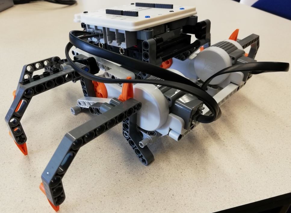
- Build Spike base
- Assemble the Arduino, Evshield and battery pack
- Build Spike motor chassis
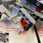
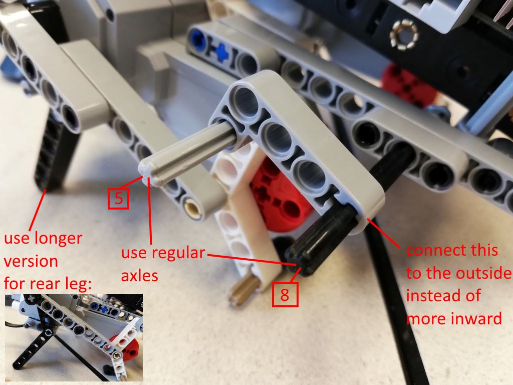
- Add the legs (follow pages 22-35 of the Spike building guide), if you use the EV3 Lego kit, you will have to make some changes to the legs:
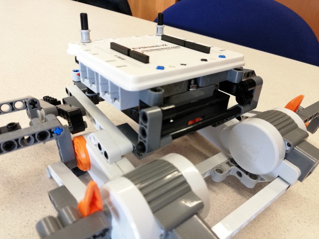
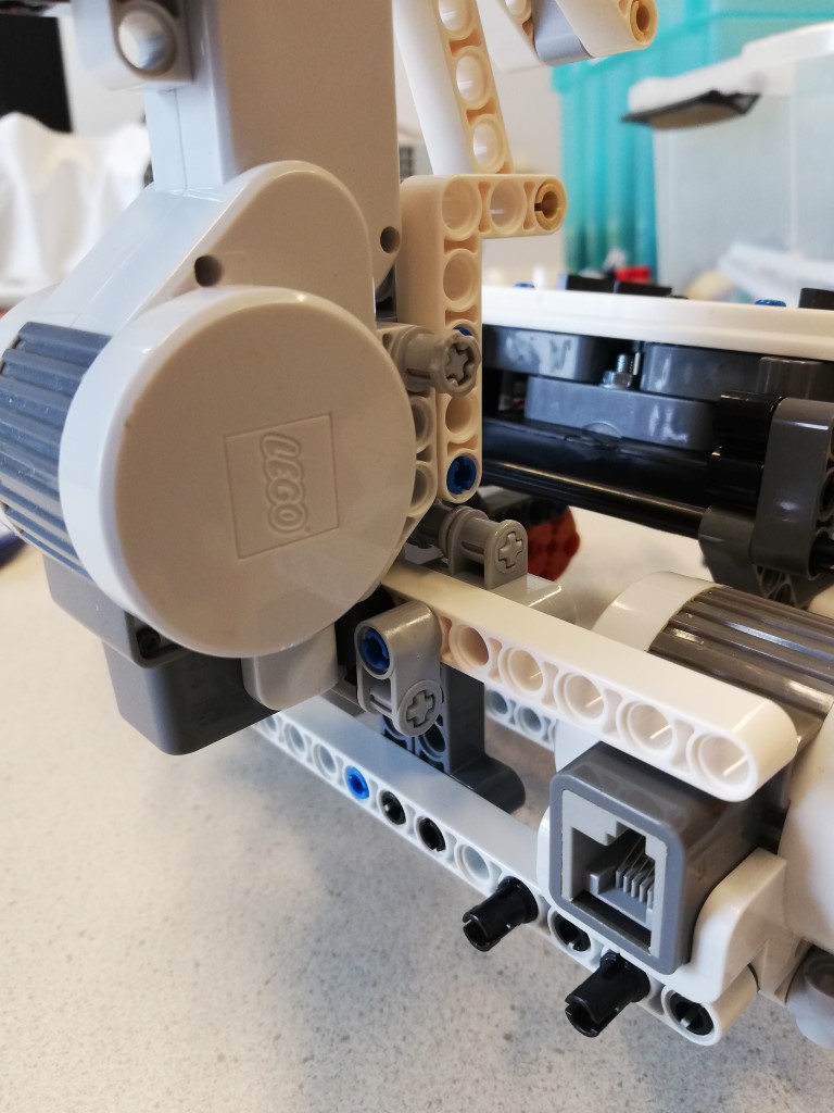
- Mount the Arduino+Evshield onto the chassis (details below)
- Program base (make it walk)
- Add ultrasonic sensor and program it
- Build the sting tail (from guide: slide 38-66) and program it
- Add claws
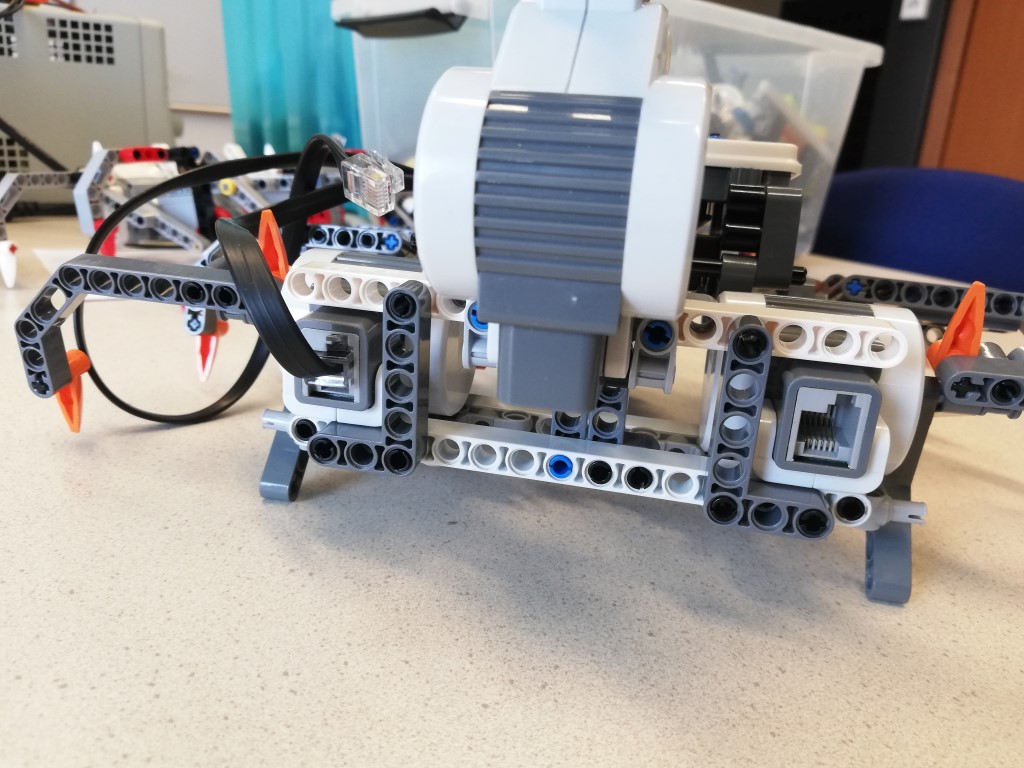
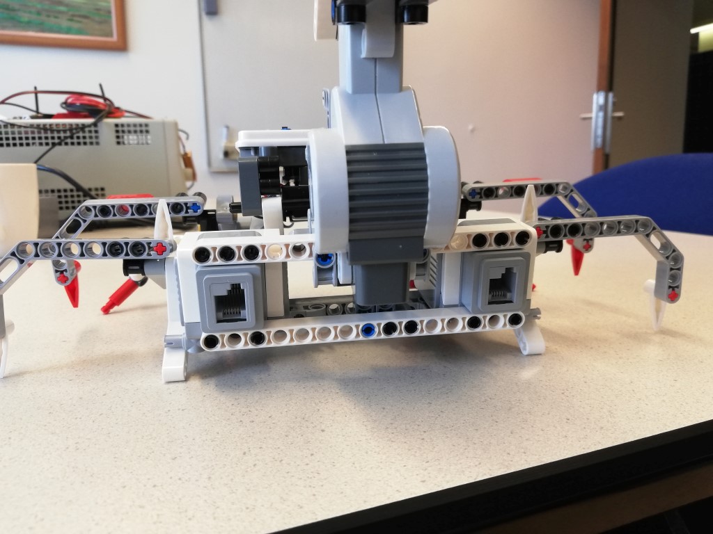
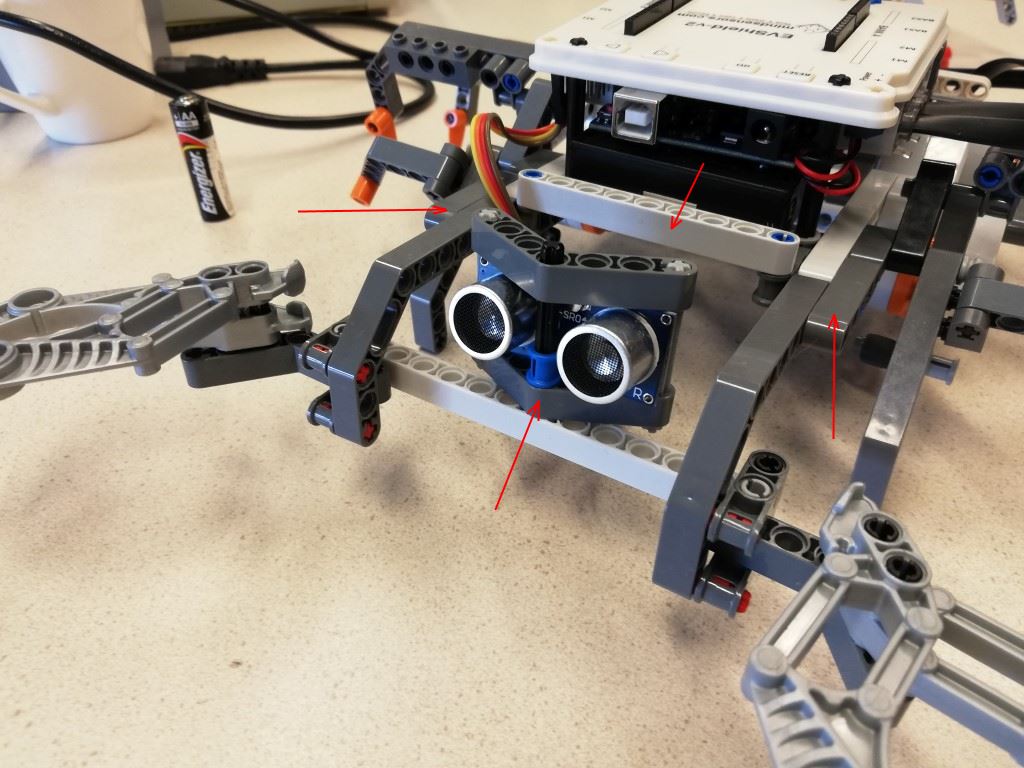
Mount the Arduino+Evshield onto the chassis
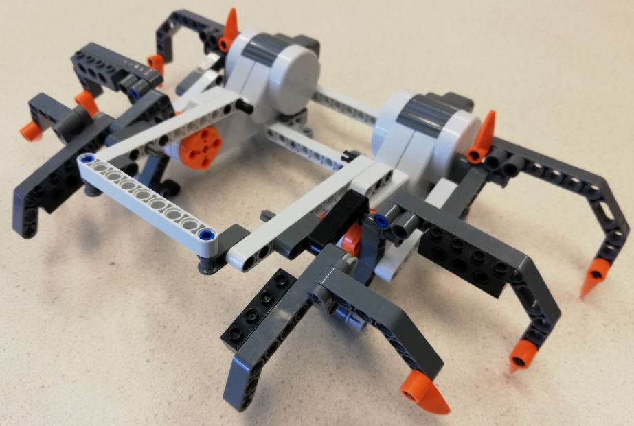
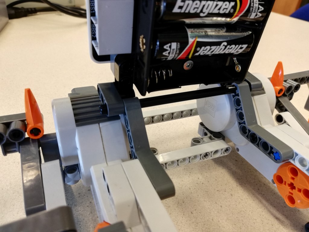
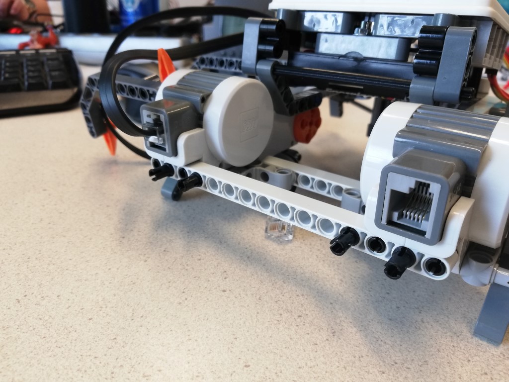
The chassis should look like:
Add connection for battery case:

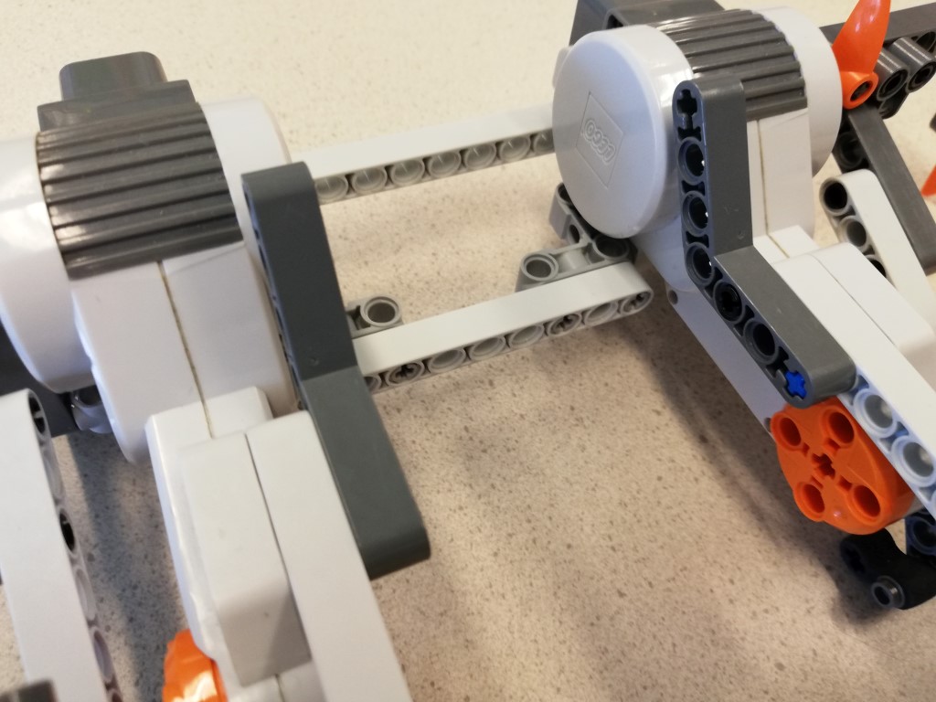

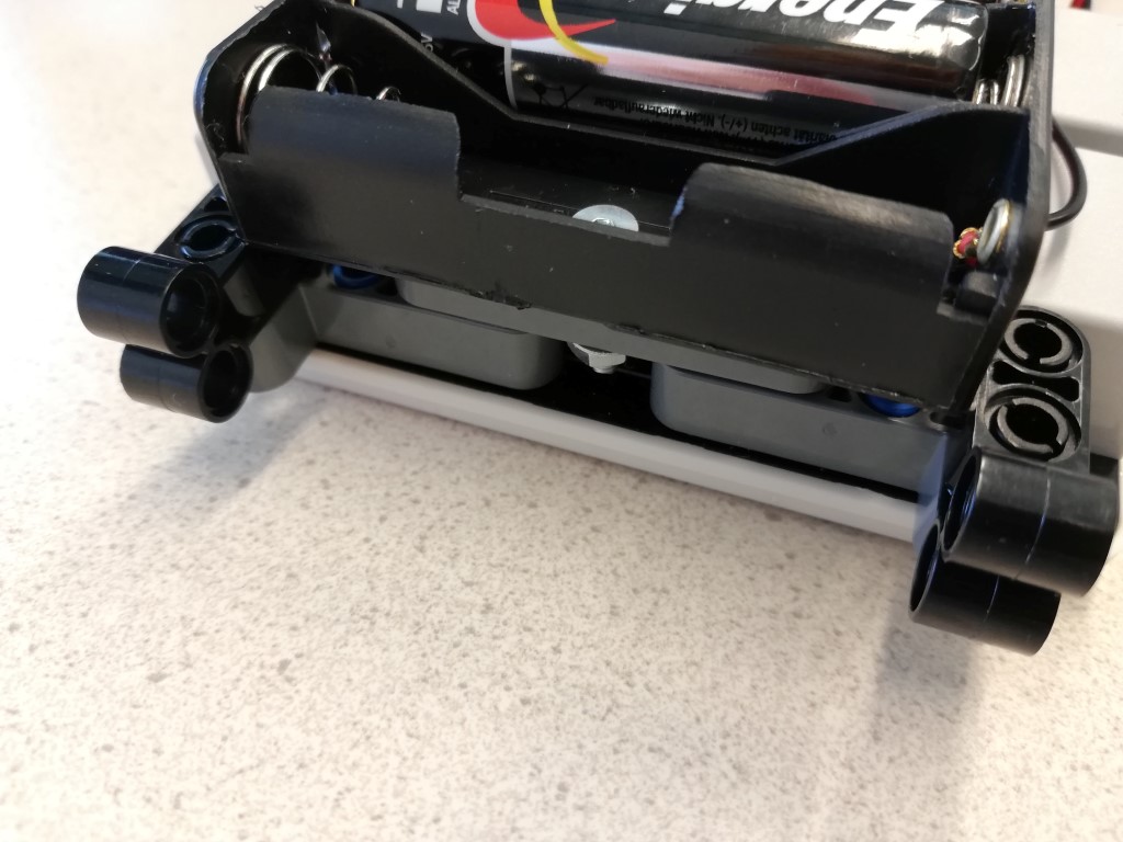
And mount it onto the chassis:
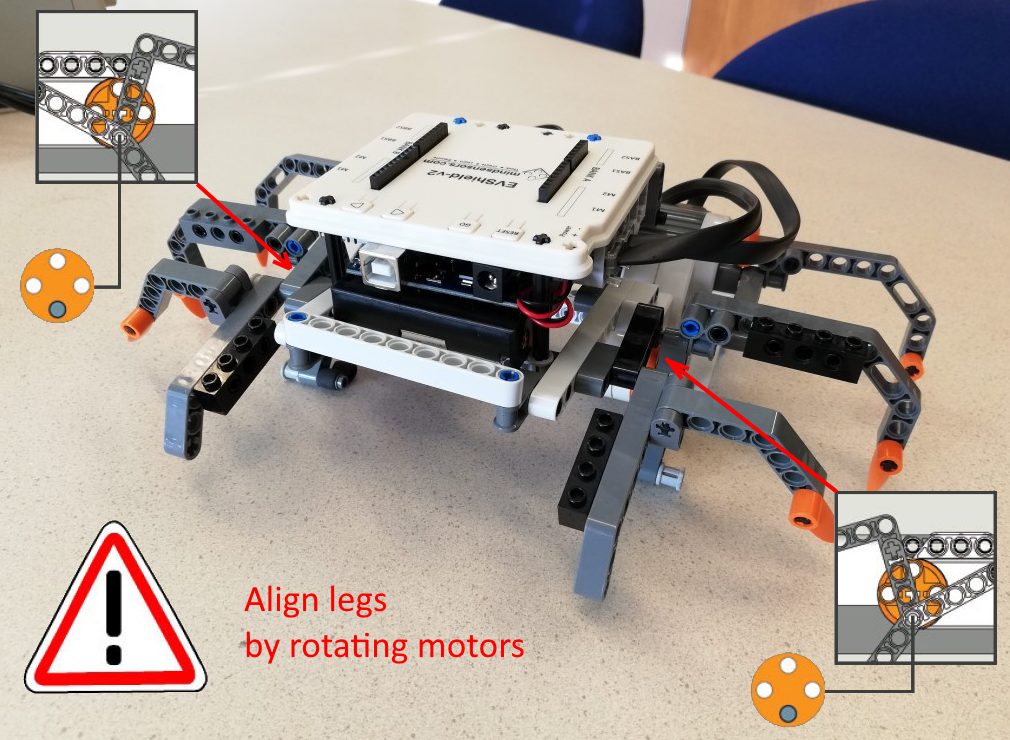
Connect two wires to the motors, insert them in port M1 and M2 of Bank A of the Shield:
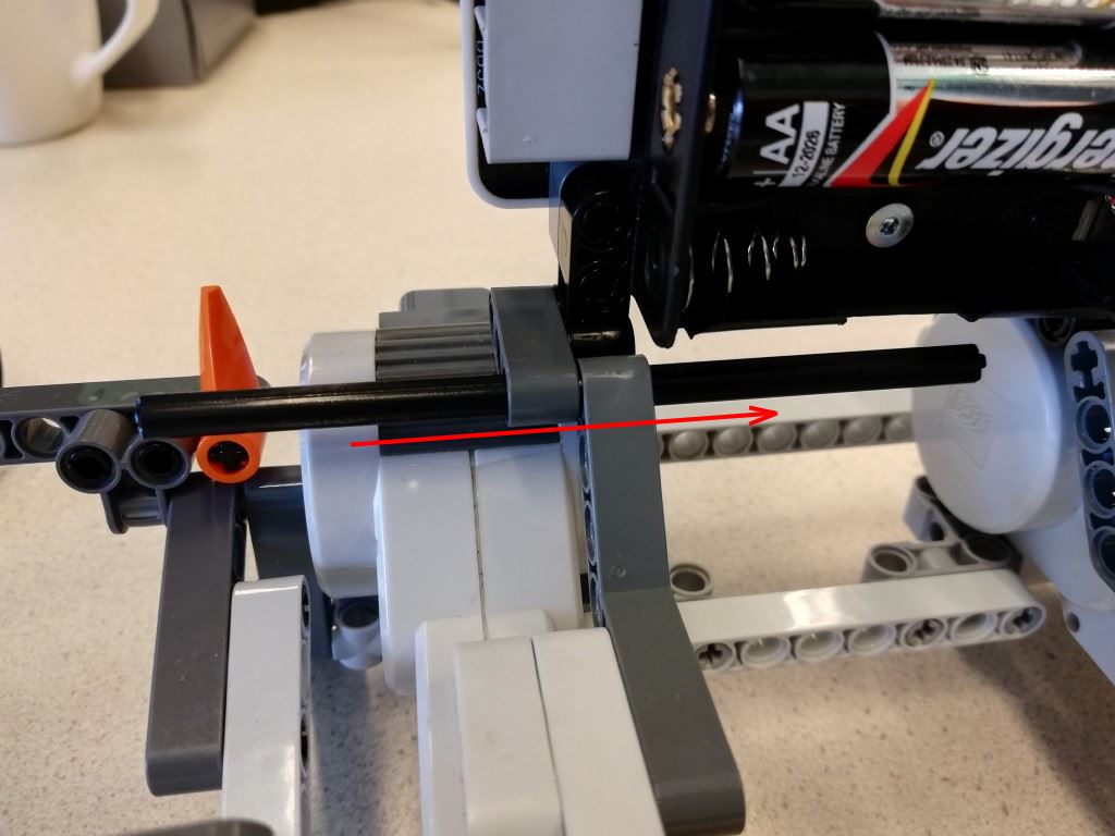
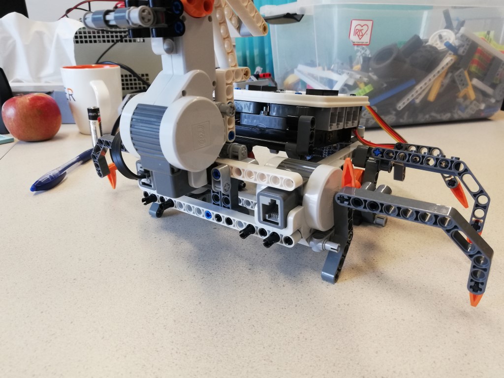
Before you start driving the creature, align the legs:
Program base (make it walk)
It is assumed you already have some basic knowledge on how to use the Arduino IDE, if you do not have that, check out the presentation of the lecture, or look here
Download the example Arduino sketch evshield_test_drive.ino and open it in the Arduino IDE.
Compile it (Sketch > Verify/Compile). If you get an error like "fatal error: EVShield.h: No such file or directory", you have not installed the EVShield library yet. Check out this installation guide on how to do that.
Connect the USB cable to the Arduino. Check the board type (Tools > Board) and connection (Tools > Port), then upload the sketch (icon with arrow or Sketch > Upload).
Test: If you press the Go-button on the shield, the Spike should start walking. Pressing the left-arrow button should reverse the direction. Tip: if you insert batteries, the spike can walk without the USB cable attached.
If you want, you can make the Spike walk faster by setting the variable speed to SH_Speed_Medium.
Add ultrasonic sensor and program it
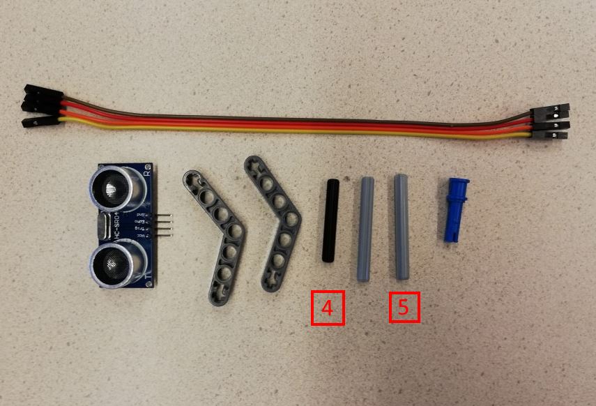
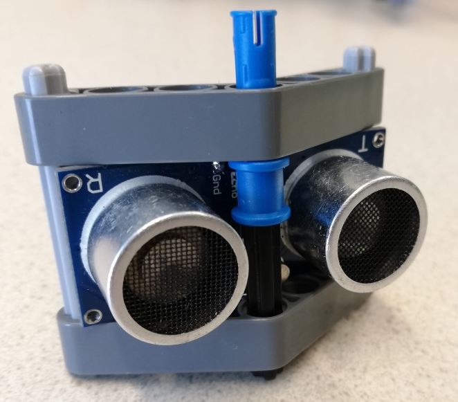
Build a holder for the ultrasonic sensor:
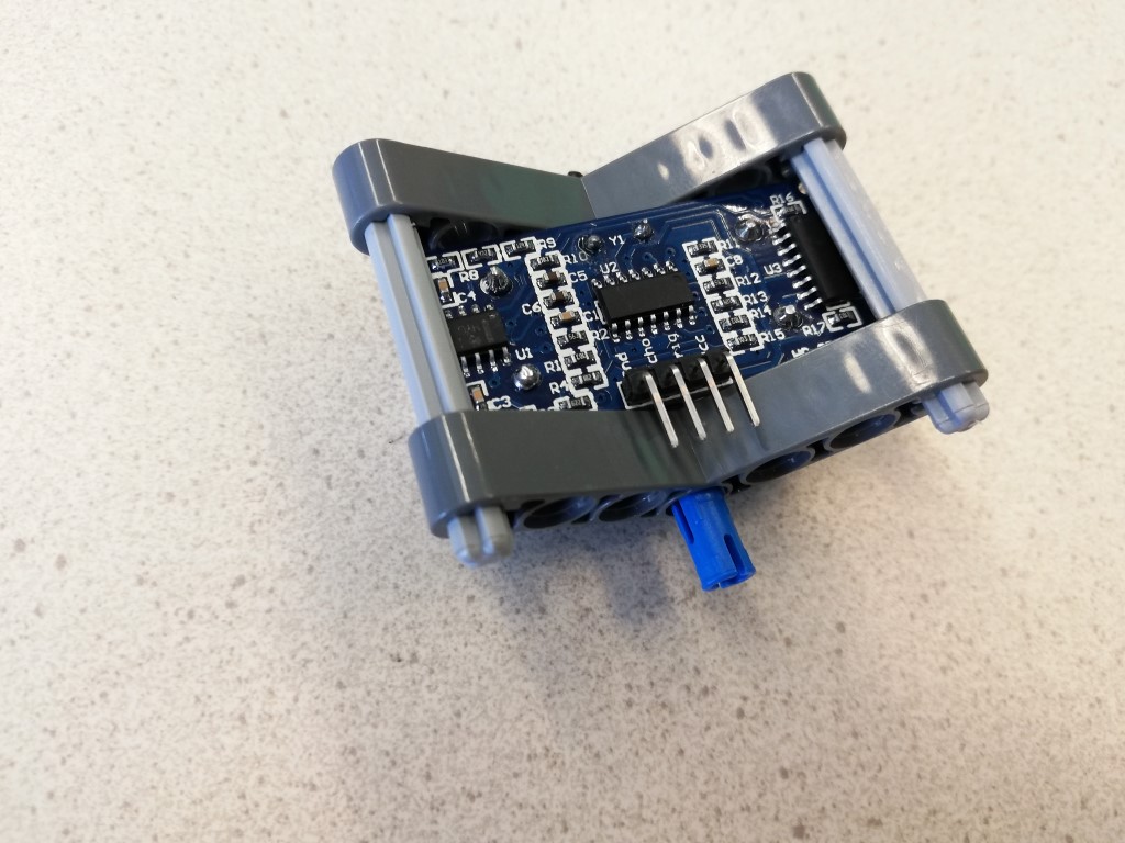
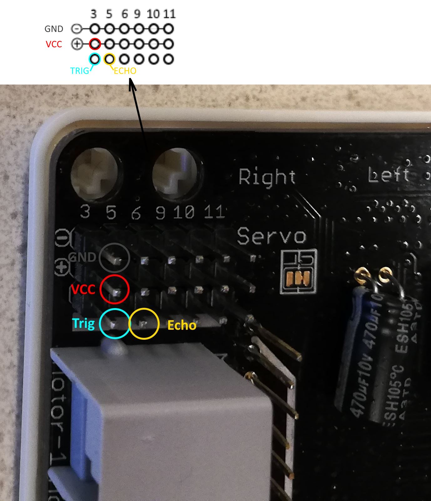
We will connect the wires to the servo-headers of the shield which are at the back (the bottom). The servo-headers have one row of pins connected to pins 3, 5, 6, 9 10, and 11 of the Arduino, and a row connected to GND (-) and VCC (+), which gets 5V if a power source is connected to the shield (eg. a battery pack). Power via USB cable is not sufficient (the output will not be 5V!). Connect the ultrasonic sensor using female-female jumper cables to the header pins as indicated:
Troubleshooting
- Does the Spike run on batteries? (power via USB cable does not work for the servo pins!)
- Double check if the wires are connected to the right pins (Trig to pin 3, Echo to 5)
- Do the defined pins in the program: TRIGGER_PIN 3 and ECHO_PIN 5, match the wiring?
- Check the serial monitor: while walking, is the distance displayed?
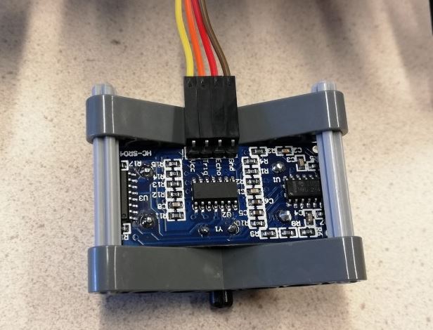
Mount the connected sensor:

Download the example Arduino sketch spike1.ino and open it in the Arduino IDE.
Connect the USB cable to the Arduino and upload the sketch.
Test: does the Spike walk backwards if you put your hand in front of the sensor?
Build the sting tail and program it
Build the tail as detailed in pages 38-66 of the Spike building guide.
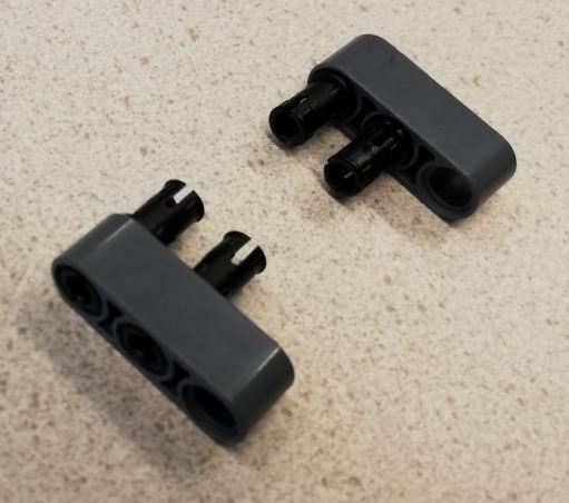
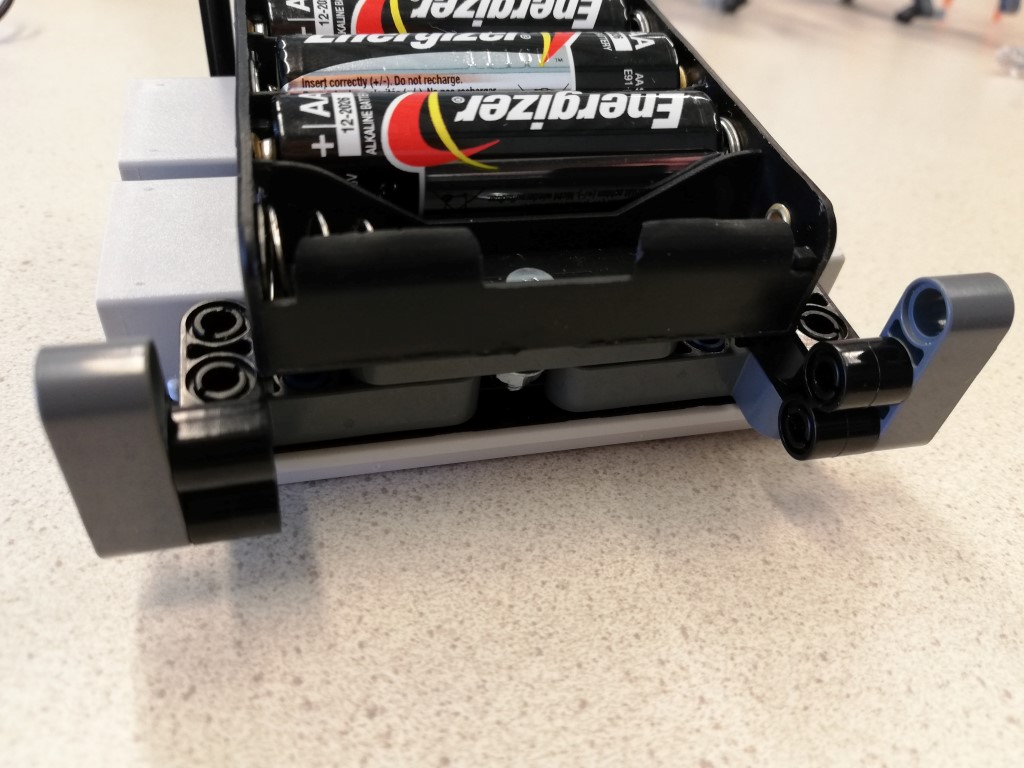
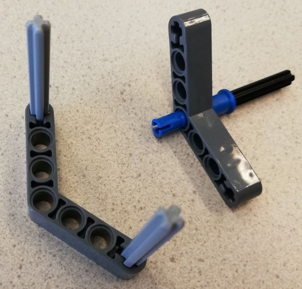
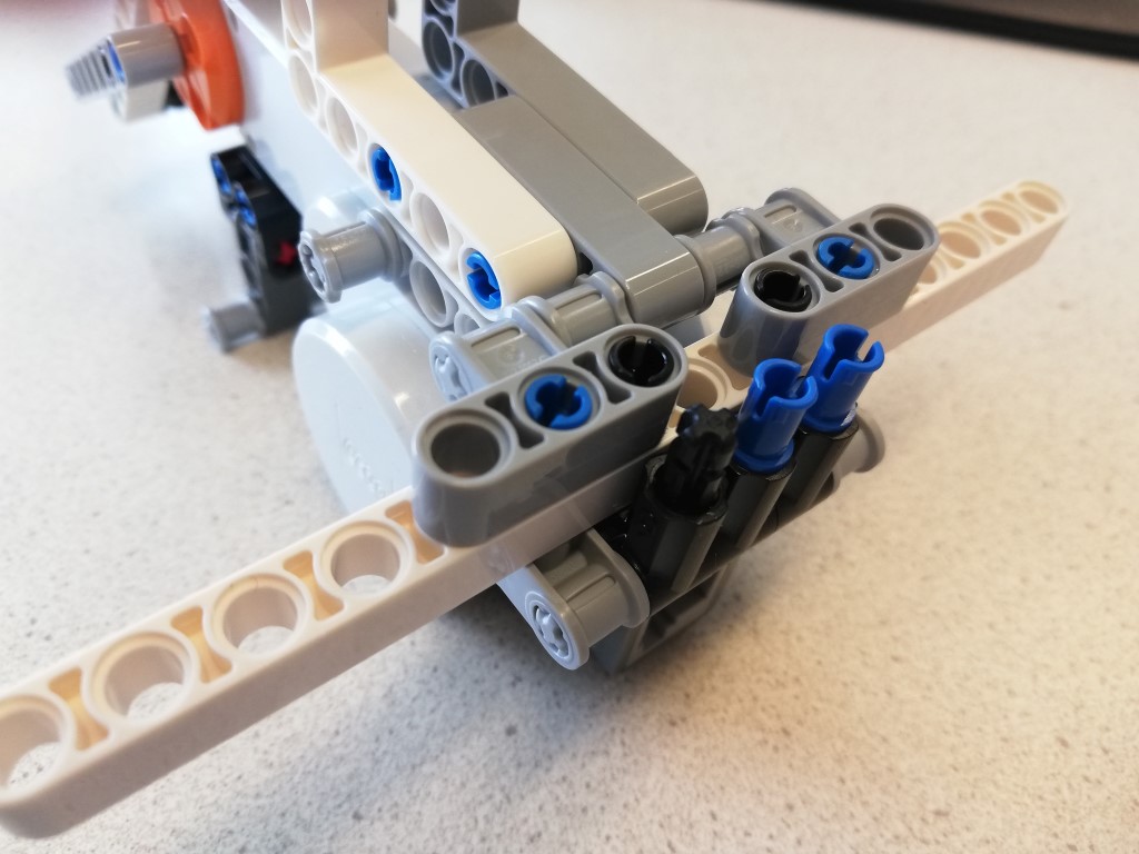
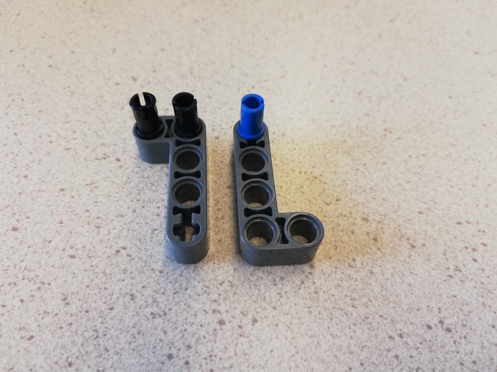
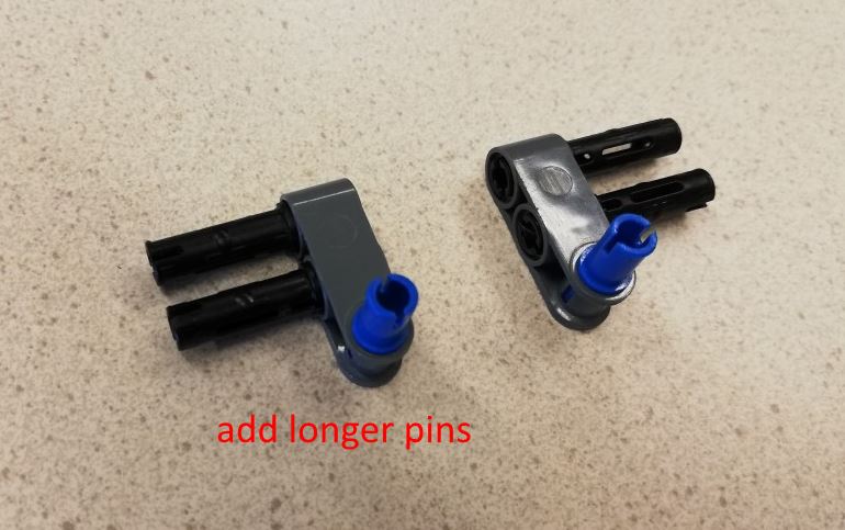
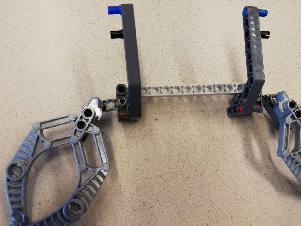
First, remove the left blue pin and replace it with a black one: Then connect it to the chassis:

If you have an EV3 based model, the connection is a little different:

Connect the motor of the tail to port M1 of Bank B. Connect the touch sensor to port BAS1 of Bank A. Test the touch sensor with the example (File > Examples > EVShield > EVShield_tests, use example nxt_touch if you have an NXT type of sensor, or ev3_touch if you have the EV3 version).
Save the spike1 program as spike2 (File > Save as).
To program the movement of the tail, we need to add code which will do something if the ultrasonic sensor detects something very close (eg. less than 10cm).
Find the if-statement that checks the distance:
if ( distance > 0 && distance < 30 ) { // is it larger than 0 and smaller than 30 (cm)?
      // backup:
      evshield.bank_a.motorRunSeconds( SH_Motor_Both, SH_Direction_Forward, SH_Speed_Medium, 2, SH_Completion_Wait_For, SH_Next_Action_Float);
      // and continue walking:
      evshield.bank_a.motorRunUnlimited( SH_Motor_Both, SH_Direction_Reverse, speed );
    }
Add an if-statement there, so it has a separate section to handle something real close (new code is in red):
if ( distance > 0 && distance < 30 ) { // is it larger than 0 and smaller than 30 (cm)?
      if (distance < 10) {
        // stop moving
        // sting
        // wait for press of Touch sensor
        // retract
      }
      else { // backup:
        evshield.bank_a.motorRunSeconds( SH_Motor_Both, SH_Direction_Forward, SH_Speed_Medium, 2, SH_Completion_Wait_For, SH_Next_Action_Float);
      }
      // and continue walking:
      evshield.bank_a.motorRunUnlimited( SH_Motor_Both, SH_Direction_Reverse, speed );
    }
For each of the lines in the if-statement ('stop moving', 'sting', ...) you may now add code yourself. Use the documentation about for instance the motor commands. You can also use the code that is already there as an example.
Some hints:
'sting' means rotate the motor (SH_Motor_1) of the tail (which is on evshield.bank_b) one rotation in reverse (SH_Direction_Reverse) at full speed (SH_Speed_Full). Do not wait for completion (SH_Completion_Dont_Wait) and use the brake (SH_Next_Action_Brake).
To wait for a press of the touch sensor, you may use:
while (!myTouch.isPressed()) ;'retract' is the same as 'sting' but in the opposite direction.
Use the example used to test the touch sensor.
Add claws
The claws are only for decoration. If you are running out of time, you may skip building them.
Build the claws as detailed in pages 9-17 of the Spike building guide. Then connect them to the chassis:


To avoid blocking the sight of the ultrasonic sensor, attach it to the front beam (see last image).
Extra challenge
If you have time left, or like an extra challenge:
Add a down-facing light sensor which prevents it from falling off a table.