We will build a temperature sensor in this tutorial and connect it with an App. It uses an DHT11 temperature & humidity sensor and Bluetooth communication with a phone. We use a BLE-Nano here, but you can also use a regular Arduino Nano. In step 3, there is an alternative offered for the part that uses Bluetooth. There is also a Python version of this tutorial.
It consists of the following steps:
- Build circuit with the Nano BLE, display and DHT11 temperature sensor
- Show values of sensor on display
- Get values on your phone
- Document the code using comments
1. Build circuit with the Nano BLE, display and DHT11 temperature sensor
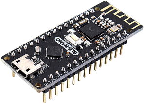
The Nano BLE as sold here is a combination of a traditional Nano with a Bluetooth BLE module, based on the CC2540 BLE Bluetooth chip.
This is the pinout of the board:
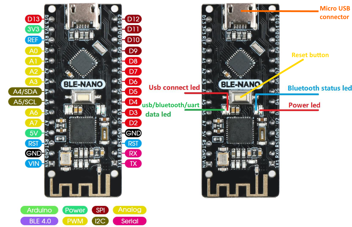
The pinout is the same as the regular Nano. Place the Nano BLE and the OLED display on the breadboard and connect them in the same way as done in this tutorial.
Please take great care: pins on your display might be in a different order! Always check the labels of the pins yourself, and connect GND to GND, VCC to 5V, SCL to SCL (A5) and SDA to SDA (A4):
Display:    Arduino:
GND         GND
VCC         5V
SCL         SCL (A5)
SDA         SDA (A4)
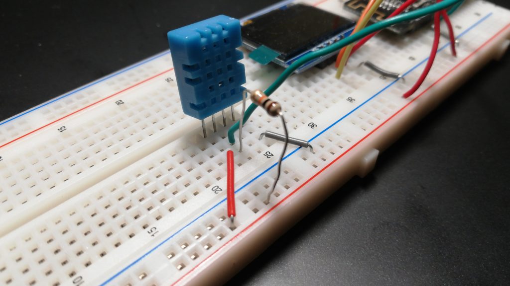
Now add the temperature sensor. Place it next to the display and connect its 3 wires to GND, 5V and the signal pin to D2 of the Nano:
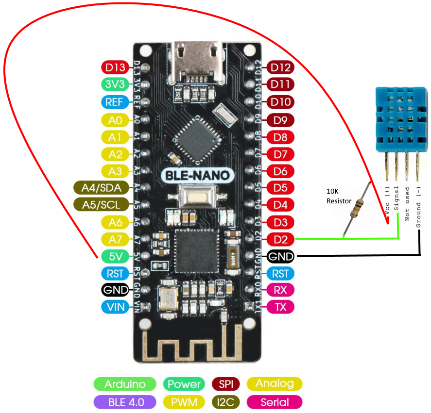
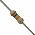
Find a 10K resistor (color code: brown-black-orange). Check the resistor guide if you do not know how to determine what a 10K resistor is. You may also use a Multimeter to check the resistance.
Mount the 10K resistor between the signal pin of the sensor and 5V:
2. Show values of sensor on display
First, install the libraries “Adafruit Unified Sensor” and “DHT library”. Go to Tools > Manage Libraries, search for the names and install both. Since there are a lot of Adafruit libraries, it might be difficult to find. If it is a long list, scroll down until you find it.
In the Arduino IDE, open the example sketch that comes with the DHT library via File > Examples > DHT sensor library, “DHT_Unified_Sensor”.
Now you have to change the DHT sensor type in the sketch. Find the #define DHTTYPE lines and make sure the DHT22 has comments in front, and remove the comments in front of the the DHT11 line:
// Uncomment the type of sensor in use:
#define DHTTYPE    DHT11     // DHT 11
//#define DHTTYPE    DHT22     // DHT 22 (AM2302)
//#define DHTTYPE    DHT21     // DHT 21 (AM2301)
Also check if the line which defines the DHTPIN has the right pin number (the pin you connected the signal line of the sensor to):
#define DHTPIN 2
Save the sketch (in the folder Documents\Arduino).
Connect the Arduino to your computer with a micro USB cable. In the Arduino IDE set the board details (your Port is probably different!) as shown below. Warning: if you use a regular Arduino Nano, the Processor is probably different (the Old Bootloader version). If the port does not show a COM… value, you might have to install a driver.

Next, upload  the sketch.
Open the Serial Monitor (Tools > Serial Monitor):

Check if correct values are displayed. It should look like:

Temperature and Humidity values should refresh about every 1-2 seconds. Breathe close to the sensor, the values should rise.
Not seeing proper values? Check if the baud rate displayed in the lower right corner (9600 in example above) of the Serial Monitor, matches the speed set in the setup() function of the sketch:
Serial.begin(9600); // baud rate for Serial Monitor connectionShow values on the OLED display
Since we already used the display in a previous tutorial, we can use that code as an example.
Add all code needed for the display from the example to this sketch. We will explain the steps below.
First, copy the code of the library (#include…) and general settings/variables (everything above the setup() function needed for the display):
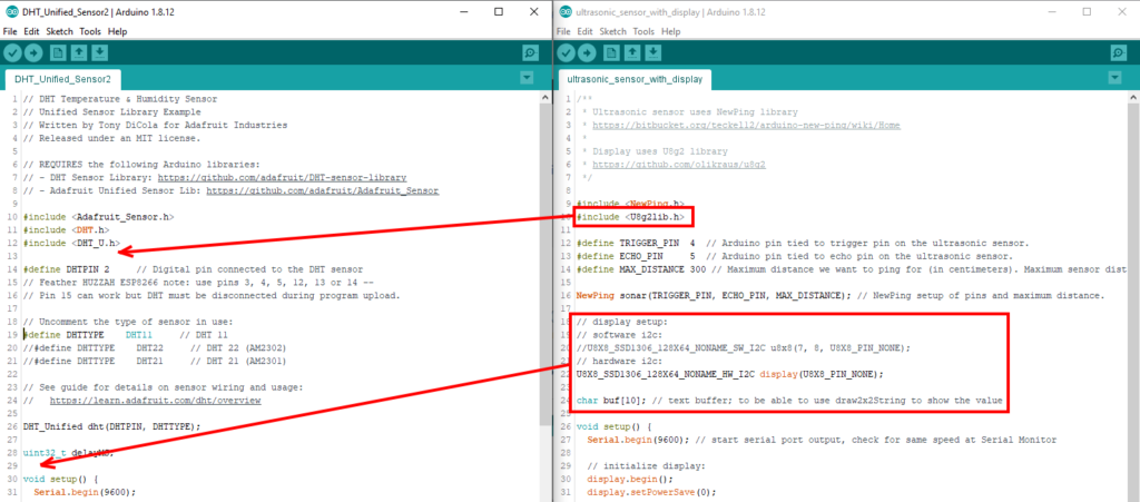
Copying works best if you can put the example sketch and the DHT sketch next to each other.
Add the code from the setup() method to the end of the setup() method of the new sketch:
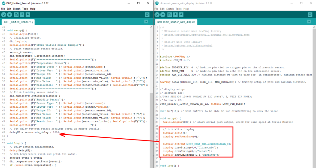
And change the last 3 lines a bit (Do you understand why? Check the library reference for info on the method drawString()):
display.drawString(0,0,"DHT sensor");
display.draw2x2String(0,2,"Temp");
display.drawString(0,7,"Humidity:");
Now the last lines from the loop() function should go into the DHT sketch at the spot after the temperature is printed:

But that code needs some modification. So instead of copying from the example, use the example below and add that after the Serial.print… statements (do not remove/replace those!):
// display temperature on display:
dtostrf(event.temperature, 3, 1, buf); // print float like XXX.X
display.draw2x2String(0,5,buf);
Now, add the lines that will print the humidity yourself: find the right spot, and copy the lines given here (above this paragraph) to that spot. Modify that code after you copied it to the right spot. On the first line, change event.temperature into event.relative_humidity. Change the second line, into a regular drawString() on position 10,7:
display.drawString(10,7,buf);The difference between the draw2x2String() and the drawString() is that the first uses double the size characters. For more info, check the library reference for info on these methods.
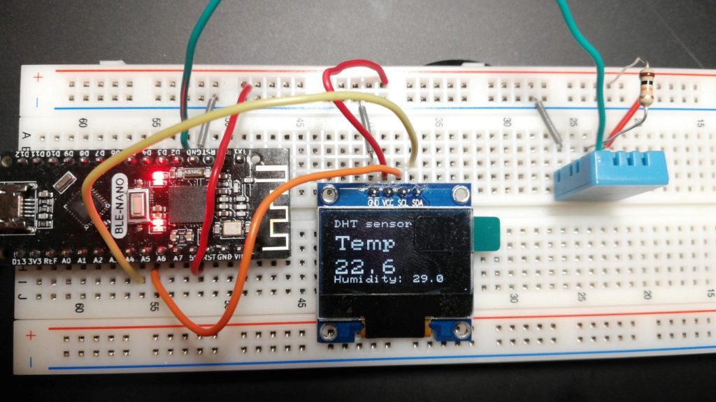
Test the sketch (upload it). Check if everything is displayed properly (on the OLED display). It should look like:
3. Get values on your phone
This step has 2 options, which you can choose one:
- Create an App which displays the values (3a)
- Use a ready-made terminal App to display the values (3b)
Obviously, the second is less work, but also less challenging and not that interesting. Especially for the project, learning the first steps of of creating Apps for your phone and make that App communicate with the electronics using Bluetooth can be very valuable! We will use App Inventor to make the App.
Do you have an iPhone?: it does not work yet on your device. Do step 3b.
Tip: if you are doing this assignment with a lot of people around you also using the BLE-Nano (eg. in a lecture room), it might be hard to find your BLE-Nano in the list of devices while connecting to it. It is possible to set a different name for your BLE-Nano. How to do that, is explained here.
If for some reason you do not have a properly working sketch, or want to try this part on its own, you can also simply connect the BLE-Nano to your computer and upload this sketch, which simulates the temperature sensor. No need to even have a breadboard: just the BLE-Nano and a USB cable are sufficient.
If you are unable to complete this step, a third alternative can be to create a Java App that displays the values on your computer.
Scroll down if you want to do step 3b.
3a: Create an App which displays the values
In this part you will learn how to deploy a ready made App to your phone and add functionality to it to show the values of the temperature sensor. It will not be a complete walkthrough of how to make the App from scratch, but it might be a starting point for you to start building Apps for your phone in the near future.
To be able to properly read the values from the lines printed in the sketch, we must adjust the sketch a bit. At the lines indicated below, remove line which prints the unit to make it easier to read the values later. And insert the extra delay for better timing of the Bluetooth communication:

Upload the sketch and check if it shows proper values without the units in the Serial Monitor:

Now close the Serial Monitor.
Now we will build the App step-by-step based on a template which already has all necessary Bluetooth functionality.
Getting started with App Inventor
First, go to the App Inventor start page. Orient yourself a bit. It has a lot of resources to get started and get help. It might be a good idea to do one of the tutorials later on, but for now that is not necessary, as this guide will help you with all steps.
Start by clicking the big orange “Create Apps!” button at the top. You will need a Google account to Log in. If you do not have this yet, create it. After you have logged in successfully, you can start building Apps.
Download this template app DHT11_receive_bt_template2.aia to your computer. If that does not work, there is a zipped version also (extract that after download).
Open the .aia template in App Inventor. Select Projects > Import project (.aia) from my computer…:

Click Choose File, then browse to the folder where the downloaded .aia file is and open that. It should look like this:
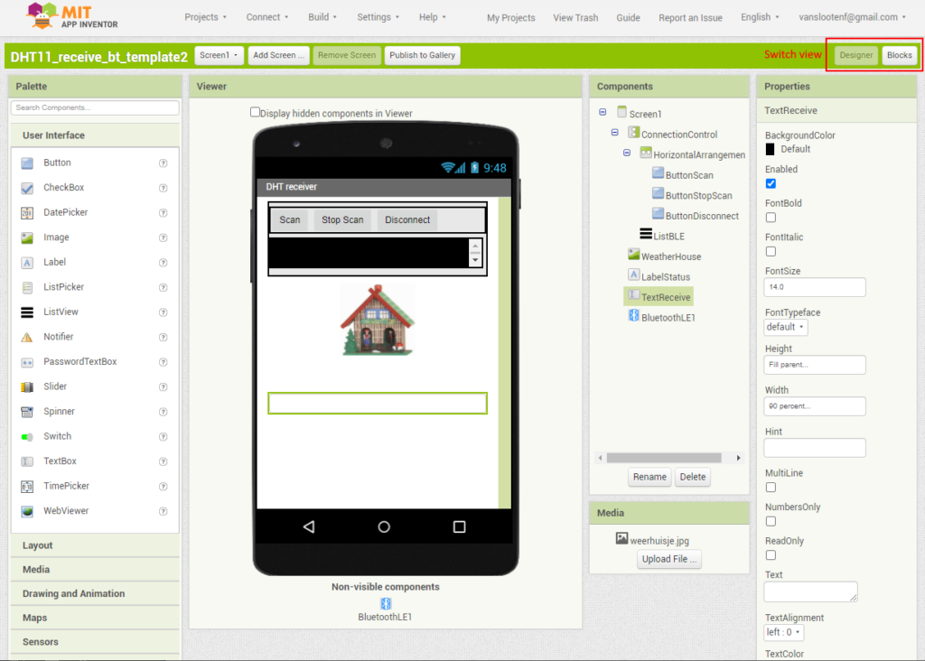
The view you see above is the Designer view, which has the userinterface of the App. Switching to the Blocks view will show the Blocks, which represents the code of the App.
This template App is already functioning, in the sense that is has a basic userinterface, and all required Bluetooth functionality. The upper part of the interface takes care of making a connection to a Bluetooth device (do not change that, as it might break the Bluetooth functionality).
We can install and run the App on your phone to test it: install the App Inventor Companion App on your phone (Google Play store/Apple App Store) and start it (explore these alternative options to run the App).
To run the App, in App Inventor, select Connect, AI Companion from the menu. Then on your phone, click “scan QR code” and scan the code on your screen. The App should then launch on your phone (screen 1 below).
You will have to do the last step again if you resume the App at a later time (eg. if you do something else for a while).
The first time you launch the App, you might have to enable Bluetooth and give the App Location permissions. In the App, select the line with “Ble-Nano” to make a Bluetooth connection with the Arduino (see screen 1 below). This should switch the App to its mode in which you can see the values coming from the temperature sensor (second screen):
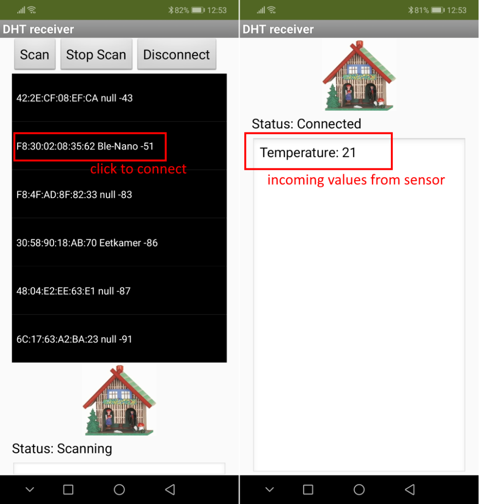
If it works, you see the incoming values in the large textbox alternating between temperature and humidity.
We can now add elements to the userinterface to properly show the values and add the necessary code blocks to display the values in the userinterface elements.
Add userinterface elements:
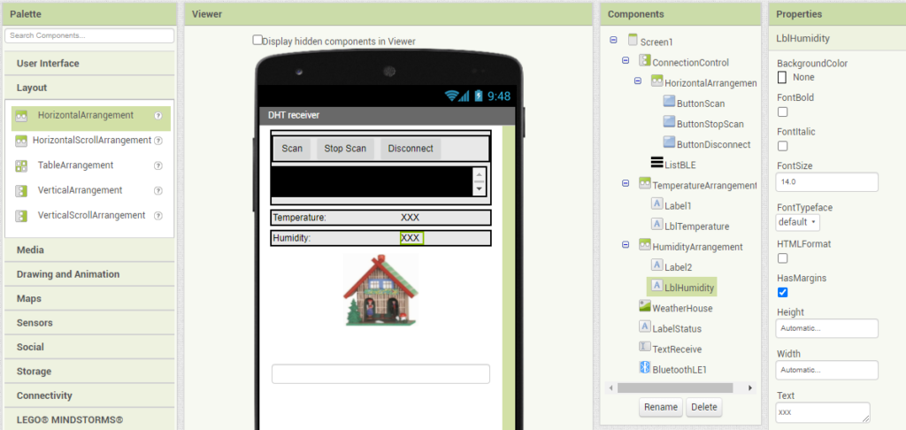
Above the image of a weatherhouse, add a HorizontalArrangement (you can find that in the Palette under “Layout”). In that, add two labels. The first one gets “Temperature:” as Text (set that at the Properties). The second one can get “XXX” or you can leave it empty. Name this second label LblTemperature, as we will need this later to show the temperature value. Your userinterface will look similar to:

Notice the HorizontalArrangement has been renamed to TemperatureArrangement as it contains the temperature labels. It’s width has been set to 90%. The width of the first label (Label1) has been set to 50%.
To quickly do the same for humidity, you can make a copy of TemperatureArrangement. Select it in the list of Components. Press CTRL + C (Copy) and then CTRL + V (Paste). This will add a TemperatureArrangement2, which you can rename to HumidityArrangement. Change the 2 labels in it to reflect their use to display the humidity. The second label should be named lblHumidity.
Add code blocks to display the values
Switch to Blocks view. Find this large piece of code blocks:

Some explanation of that:
This is the StringsReceived method of the BluetoothLE1 object. This object handles all Bluetooth communication. This method will be invoked each time a new String (a line of text) arrives. From that we can read what we are receiving. The parts of the code are explained further:
- Trims whitepace/spaces and brackets ‘(‘ and ‘)’ from any incoming text and puts the resulting cleaned text in the variable
line. - Shows the line in the TextBox TextReceive.
- Splits the line into words (breaks it up at spaces). Puts result in variable
words. - If the line contains the word “Temperature”…
- Then put the second word (from the list of words) into a new variable
temperature - If the line contains the word “Humidity”…
- Then put the second word (from the list of words) into a new variable
humidity
Those two if-then blocks should now get some code to put the values of the variables into the proper labels.
In the list of Blocks on the left, scroll down, to find LblTemperature, and click it. Find the block “set LblTemperature” Text to”:
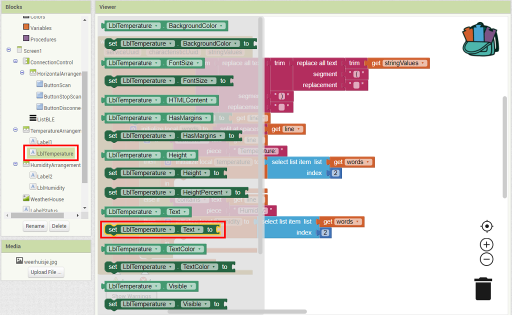
And drag that into the code, in the in-block for the temperature:

Now hover with your mouse over the temperature variable and drag the block “get temperature” to the end of that code that was just added:


Repeat the same for the LblHumidity. Add that to the part of the code that handles the humidity.
Test the App by running it again via Connect > AI Companion.
We make a final addition to the App: add a temperature warning. We will make the background of the label which shows the temperature red if the temperature exceeds 25 degrees.
Find the if-then-else Control block:

And drag that into the code after the line that sets the temperature value:

Find the Math comparison block:

Add it to the if and set it to compare larger-then:

Add the get temperature to the left side of the comparison: (hover over the temperature variable).

Add a value of 24 to the right side of the comparison:


Now, in the then-part of the if, set the background color of the LblTemperature to red. Find the appropiate blocks yourself in the list of blocks. The result should be:

Also set the background color of the LblTemperature to white in the else-part of the if (hint: you can copy blocks):

You have now completed the temperature warning. Test if it works. You can breathe on the sensor to raise its temperature. Or lower the warning temperature from 24 to for instance 22.
If you would like to learn more about this topic, read this Blog post.
This concludes step 3a. You may now continue with the last step, 4.
3b: Use a ready-made terminal App to display the values
If you have already finished step 3a, you may skip this step and directly go to step 4.
Because we do not have a ready-made App to display the values of the sensor on our phone (we might create that later in this course) we will use a generic Terminal App to send and receive texts from the Nano BLE. You can see this as a kind of a chat app, which we use to communicate with the Nano BLE. In this case, we ask for a value, and the sensor returns that value.
The Nano BLE has serial communication build in. We can use this to exchange text messages by simply printing to the Serial port. This is what our sketch already does, for example, to print the temperature:
Serial.print(F("Temperature: "));
Serial.println(event.temperature);
Serial.println(F("°C"));
Add a Terminal App to your phone

To be able to see that printed text output on your phone, you must install a Terminal App that supports BLE. Search the Play store for “arduino ble terminal”. You will see there are a lot of apps like this. For Android, the app Serial Bluetooth Terminal by Kai Morich is recommended. This app has been tested and works fine.
Other app? If you pick another app, make sure it supports Bluetooth LE/BLE. For iOS, BLE Terminal HM-10 works.
Connect with your phone
Start the Terminal App you just installed (on your phone). If being asked for Location permission, allow this (it is needed to locate the device). Click the connect icon in the titlebar:

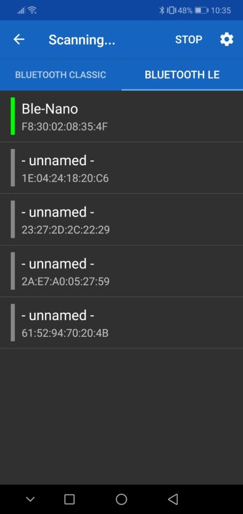
Allow to turn on Bluetooth. If it does not come up with a list of devices to connect to, go to the menu, pick “Devices” and go to the tab “BLUETOOTH LE”. Press scan. If your Nano BLE is on, it should appear in the list as “Ble-Nano”. Click it to connect to it. You should see the terminal screen like the second screenshot:
Troubleshooting: If it is open, close the Serial Monitor of the Arduino IDE. Disconnect the USB cable, wait 10 seconds, and reconnect it. On the App, if you see garbage on the screen, disconnect (use the connect/disconnect icon in the top bar), press the clear icon (the bin) and retry connecting (never connect while a sketch is uploading!). If still seeing garbage, try changing the display mode to Terminal (in the App, go to Settings, Terminal, Display mode). And under Settings, Receive, make sure Newline is set to “CR+LF”.
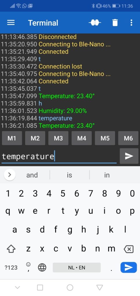
You should now see a continues flow of lines with temperature and humidity readings. Instead of this, we want the Nano BLE to only send values when we request it. We can type commands (texts) in the textfield at the bottom, just like any chat app. For instance, if we type “temperature” (or a “t”) is should give us the temperature.
To realize this, we add a variable at the top of the sketch (before the method setup()):
char char1 = '-'; // first character of command to receive via chatThis allows us to store (remember) the first character, which we can use to select the appropriate action: a ‘t’ means “show the temperature”, a ‘h’ means “show the humidity”.
To get the charachter, we need to read it from the BLE connection. Add the following piece of code at the end of the loop() method to realize this:
if(Serial.available()){
    char1 = Serial.read(); // read first character of string received
}
Add comments in front of the code which explain what it does.
To check what character was sent, we can now use an if-statement like:
if( char1=='t' ) {
    // first character received was a 't'
}
In the loop(), find the code which displays the temperature at the Serial connection (look for Serial.print...). Put the if-statement there and place the 3 lines that display the temperature inside the brackets {...} of the if-statement. Do the same for the humidity. Check the condition of the if-statement for the humidity to char1==’t’.
On your phone, disconnect the connection with the Terminal App. Then upload the sketch. Connect again and check if it works. You should now see no measurements, only when you request them (type a ‘t’ or ‘temperature’ and press Send):
You might notice that when you type a command, the text remains in the text-entry field. To prevent that, go to settings, “Send”, and turn on the option “Clear input on send”.
If the app works as intended, you can continue to the next step.
Tip: if you are unable to complete this step, you may also create a Java App that displays the values on your computer.
4. Document the code using comments
For the Arduino sketch, add more comments to the parts of the code that you added/modified. Use multi line comments or single line comments. Use the comments to explain how the code works. If you are a student of mine, it must be clear for us, when we review your code, that you understood its purpose.
Some examples of comments:
/*
Example of a multi line comment.
This is the second line of the comment.
*/

// Example of a line of code with comment at the end of the line:
Serial.println("Start of distance measurement"); // display text on serial output
At the top of the sketch, add multi line comments with a general description of the sketch and have your name (and student number) on the first line of that block of comments.
Summary
With this tutorial you have familiarized yourself with building an electronic circuit using a breadboard and you have used the Arduino IDE to program the Arduino with a sketch.
In addition, you have learned the following.
- Made your own sketch by combining different examples and modifying existing code
- Incorporate a Bluetooth connection to a circuit to your phone
- Exchanging information and values of sensors via the Bluetooth serial connection
- Made your first steps to creating an App on your phone
- Adding comments to code
Learn more
You can further test controlling an Arduino circuit by an App on your phone, by testing the gamepad with the Dabble App. Or connect an RGB led and use your phone to change its color (in the example, you do not need the HM10 module, as the Nano BLE already has a built-in Bluetooth module, so skip step 2).


