In this tutorial, we will build a laser distance Sensor with a Raspberry Pi Pico and CircuitPython, using a VL53L1X Time-of-Flight (TOF) sensor.
In this tutorial you will learn to build a distance sensor. Starting with the basic steps to connect electronic components and programming the Raspberry Pi Pico in Python. Next, use a laser distance sensor to sense the distance to an object nearby and an OLED display to show the measured value of the distance sensor.
The tutorial consist of the following steps:
- Setup the Raspberry Pi Pico
- Connect and test the OLED display
- Connect and test the Ultrasonic sensor
- Add comments to the code
What you need
- Breadboard, wires, micro USB cable
- Raspberry Pi Pico
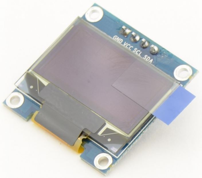
- An OLED display, eg. this 0.96 inch OLED Display (128*64 pixels)
- The laser distance sensor: VL53L1X
- A buzzer
1. Setup the Raspberry Pi Pico
First, install the latest version of CircuitPython to the board. Download the .UF2 file for the regular Pico here, or for the Pico W/WH here. Connect the USB-cable to the board. While pressing the BOOTSEL button on the board, connect the other end of the cable to your computer. Continue to hold the BOOTSEL button until a drive appears: a new drive labelled ‘RP…’ will appear in your Windows Explorer (or Finder on a Mac). In the example this is the D: drive, but it might be different on your computer:
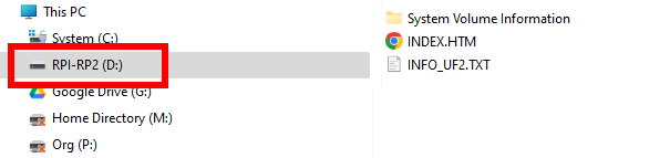
Now drag the downloaded .UF2 file to that drive. Now wait for the drive to disappear and then re-appear (labelled CIRCUITPY).
For more detailed steps check out the tutorial “Installing CircuitPython”.
Check the Raspberry Pi Pico, blink the onboard LED
To start writing code, you need an editor. We recommend to use Thonny. So, download and install that. Alternative editors are the Mu Editor or Visual Studio Code.
After you have installed the editor, you can create your first Python file. Select File > New. And copy-paste the code below into the editor.
# SPDX-FileCopyrightText: 2021 Kattni Rembor for Adafruit Industries
#
# SPDX-License-Identifier: MIT

"""Example for Pico. Blinks the built-in LED."""
import time
import board
import digitalio

led = digitalio.DigitalInOut(board.LED)
led.direction = digitalio.Direction.OUTPUT

while True:
    led.value = not led.value
    time.sleep(0.5)
This code comes from the first part of this tutorial, at “The LED blinks!”. If you want to learn more of how exactly it works follow the steps in that tutorial!
The first lines start by importing several modules using the import statement. A module is a set of code which can be reused easily. It contains code to avoid you having to ‘re-invent the wheel’ all the time.
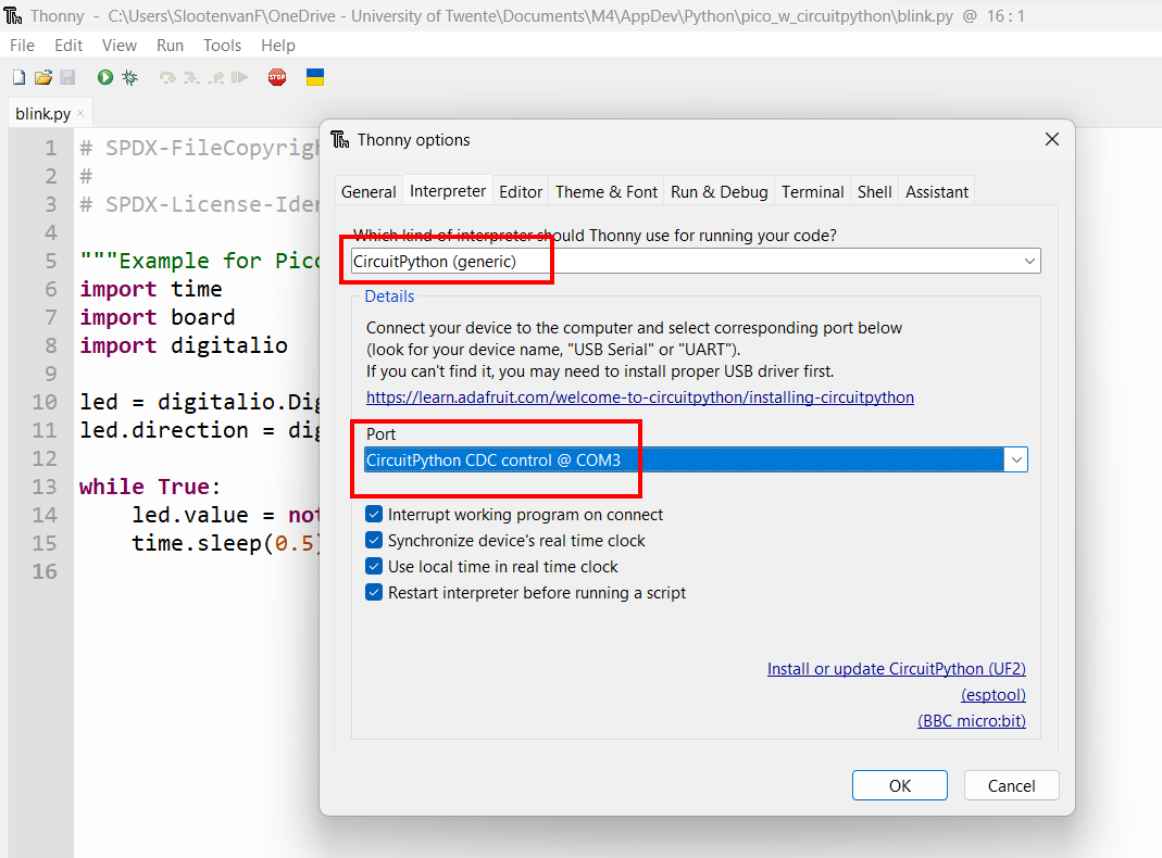
Before you can run the script, first connect the Raspberry Pi Pico board to your computer using a USB cable. Wait a few seconds to let it initialize. Then, in the Thonny editor, choose Run > Configure interpreter and set the interpreter to CircuitPython and choose the active port (in Windows: the one that has CircuitPython CDC control…):
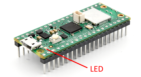
Close the Options Window (Press Ok). Now, you should be able to run the script. Press Run ![]() and see what happens… If all is well, the LED next to the USB connector on the board should start blinking.
and see what happens… If all is well, the LED next to the USB connector on the board should start blinking.
2. Connect and test the OLED display
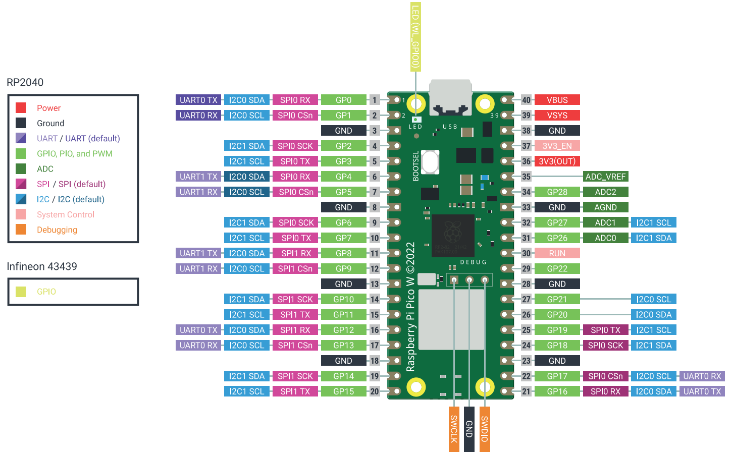
The 0.96 inch OLED Display (128*64 pixels) is an i2c module, which makes it easy to connect as it has only 4 wires. It is assumed you have some basic understanding of using electronics and wiring a breadboard. For making the right connections you need the pinout diagram of the Pico:
See the image below. Pins of the display are on the board itself. Please take great care: pins on your display might be in a different order! The one below has GND-VCC-SCL-SDA, but yours might be different!
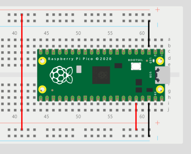
Unplug the USB cable. Plug the Pico onto the breadboard. Start wiring the power lines (blue and red lines on the breadboard) to GND and 3V3 of the Pico:
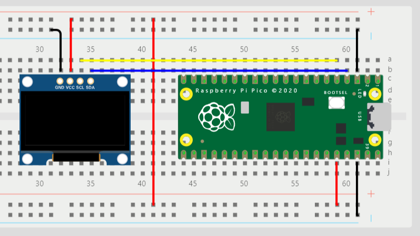
Then plug the display onto the board and wire it:
Display:    Pico:                   Wire color in diagram:
GND         GND                     black
VCC         3V3                     red
SCL         pin 5 (I2C1 SCL/GP3)    yellow
SDA         pin 4 (I2C1 SDA/GP2)    blue
(you are free to choose any other color for the wires)
Download example code
To test the display, you can use this example script: display.py. Open it in the editor. Please be aware that the script is saved in your Download folder. If you do not want this, Select File > Save As to save it to another folder, for instance the Documents\Python folder.
After you double check the wiring from the previous step, plug in the USB cable.
Before you can run the example, you must install some CircuitPython libraries used by it. Go to circuitpython.org/libraries and scroll down to the “Bundles” section. Download the latest bundle for your version of CircuitPython. Extract that zip-file and copy the folders and files below (they are in the lib folder of the zip-file) to the lib folder of the drive (eg. D:\lib) on the Raspberry Pi Pico:
folders:

adafruit_bitmap_font
adafruit_bus_device
adafruit_display_text

files:

adafruit_displayio_ssd1306.mpy
adafruit_ssd1306.mpy
adafruit_vl53l1x.mpy
The last one, adafruit_vl53l1x.mpy, is used in the next section.
Press Run ![]() and check if “Hello World!” is shown on the display.
and check if “Hello World!” is shown on the display.
You can also run a simulation of this circuit here and take a closer look at the wiring.
3. Connect and test the laser sensor
This part of this tutorial introduces the VL53L1X Time-of-Flight laser sensor.
If you bought it like this:
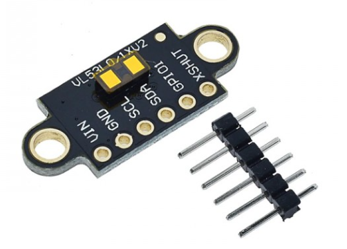
You will first have to solder the header pins.
Disconnect the USB cable before you continue.
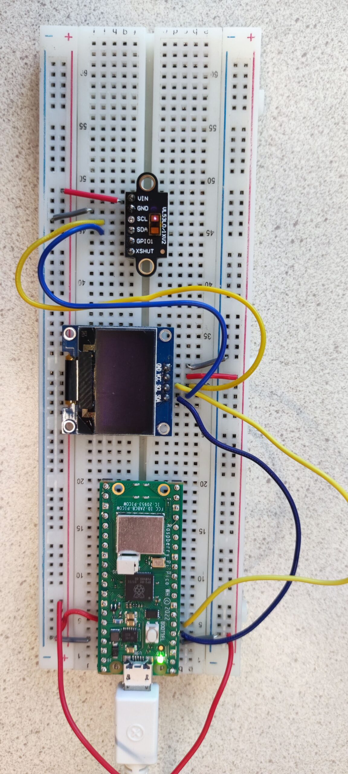
To use this sensor, you can connect it to power (GND and VCC) and connect the SLC and SDA pins to the same wires (yellow & blue below) as the display.
To test the sensor, you can use this example script: vl53l1x_display.py. Open it in the editor and save it to your documents folder.
After you double check the wiring from the previous step, plug in the USB cable. Press Run ![]() and check if measured values of the distance measured are shown on the display.
and check if measured values of the distance measured are shown on the display.
4. Add comments to the code
Add more comments to the part of the code that you added/modified. The comments should explain, in your own words, what this code does. Use multi line comments or single line comments. Some examples:
"""
Example of a multi line comment.
This is the second line of the comment.
"""

# Example of a line of code with comment at the end of the line:
print("Start of distance measurement") # display text on standard output
At the top of the script, add general comments. The first line of comments should contain your name and student number. Add at least one more line which explains the general meaning of the script as a whole (what does it do?).
Summary
With this tutorial you have familiarized yourself with building an electronic circuit using a breadboard and you have used an editor to program the Raspberry Pi Pico with a script.
In addition, you have learned the following:
- Adding components like a display and a sensor to a breadboard and wiring them
- Using an example script to test the components
- Use and setup modules
- Add code to an existing script
- Explain and document code by adding comments to code
More information
- Programming Raspberry Pi Pico with Arduino IDE (Pico W compatible)
- More Raspberry Pi Pico Projects, Tutorials and Guides
- Using the VL53L1X Time-of-Flight Distance Sensor (Arduino version)


