
Learn more about simulating a physical prototype. Wokwi is a great simulator that you can use to build your electronics projects online, without the need to get components, wire them on a breadboard and then test. If you combine it with Chat GPT to do the coding, you can have your prototype up-and-running in literally minutes.
Browse examples
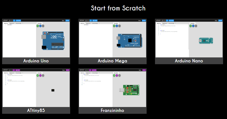
From the Wokwi homepage, you can browse featured projects, or start from a template setup. Eg. click ‘Pi Pico’ for a Raspberry PI Pico project, or from the guides choose either “MicroPython” or “CircuitPython” to get started with those. For an Arduino-based project click ‘Arduino’, then pick your model from there:
Or get started with an example that already looks promising, and go from that (import it to your own projects via ‘Save a copy’).
Browse some of my projects:
Getting started: Editor & Keyboard shortcuts
Wokwi has a lot of online help pages. Like a page describing the diagram editor. And keyboard shortcuts can also come in handy.
Below are two example of getting started, the first with an Arduino, second with a Raspberry Pi Pico.
Start with a breadboard & Arduino Nano
You may also follow along this video tutorial:
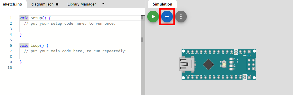
Start with a new project, pick a micro controller, like the Arduino Nano. Then add a breadboard. First click the ‘+’:
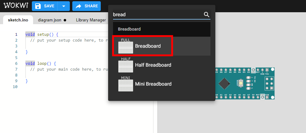
Then type breadboard and pick the full size:
Place the Arduino (drag it on the right spot on the board) and add more components. Here we add an LED and a 220 Ohm resistor:
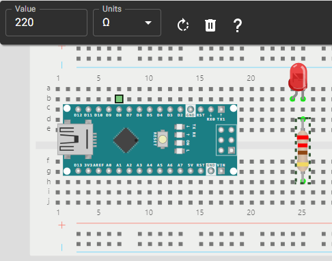
While the resistor is selected, rotate it ![]() (keyboard: press ‘r’) and set the proper value of 220 Ohm. The LED must be flipped also, using the flip icon
(keyboard: press ‘r’) and set the proper value of 220 Ohm. The LED must be flipped also, using the flip icon ![]() (keyboard: press ‘p’).
(keyboard: press ‘p’).
Add wires (draw lines by clicking). To change the color of a wire, select it, and choose the color:
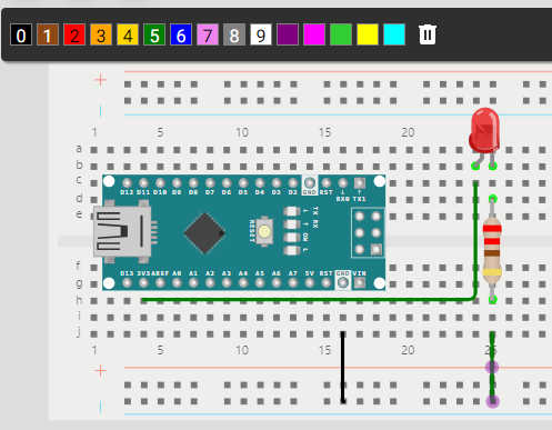
As you can see we connected the anode (A) of the LED (left leg in picture) to the 3.3V pin of the Arduino, and the other (C, cathode) to Ground (GND), via the resistor. This should make the LED turn on if we run the simulation (press the Play-icon ![]() ):
):
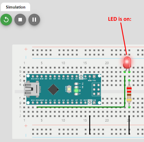
Stop the simulation (stop icon).
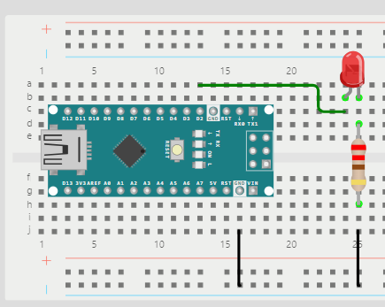
Now, remove the green wire by selecting it and then press the Delete key on your keyboard (or use the trash icon). Draw a new wire to connect the LED to pin D2:
Now we will insert code from the Blink example into the code pane (sketch.ino):
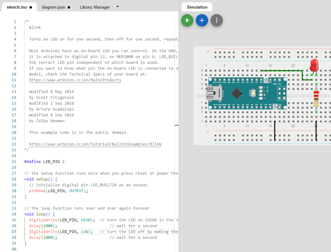
Note that at line 25, the #define is added to reflect the pin we use. And at lines 30, 35, 37 the LED_BUILTIN is replaced by that LED_PIN.
If all went well, you should now see a blinking LED if you click the Run icon.
See my version of this project here.
Start with a breadboard & Raspberry Pi Pico
Start with a new project, pick a micro controller, like the “Micropython Pico W”, choose “MicroPython” from the beginner templates. Then add a breadboard. First click the ‘+’:
Then type breadboard and pick the full size:

Rotate the Pico (press the R key on your keyboard) and place it (drag it on the right spot on the board) and add more components. Here we add an LED and a 220 Ohm resistor:

While the resistor is selected, rotate it ![]() (keyboard: r) and set the proper value of 220 Ohm. The LED must be flipped also, using the flip icon
(keyboard: r) and set the proper value of 220 Ohm. The LED must be flipped also, using the flip icon ![]() (keyboard: p).
(keyboard: p).
Add wires (draw lines by clicking). To change the color of a wire, select it, and choose the color:

As you can see we connected the anode (A) of the LED (left leg in picture) to the 3V3 (3.3V) pin of the Pico, and the other (C, cathode) to Ground (GND), via the resistor. This should make the LED turn on if we run the simulation (press the Play-icon ![]() ):
):

Stop the simulation (stop icon).
Now, remove the green wire connected to the Anode of the LED by selecting it and then press the Delete key on your keyboard (or use the trash icon). Draw a new wire to connect the LED to pin GP15:

You can hover over the pins to see its label (second picture above).
Now we will insert code to make the LED blink into the code pane:
import machine, time
time.sleep(0.1) # Wait for USB to become ready
print("Hello, Pi Pico W!")

led = machine.Pin(15, machine.Pin.OUT) # LED connected to GP15

while(True): # Repeat forever
    led.high()
    time.sleep(1)
    led.low()
    time.sleep(1)
If all went well, you should now see a blinking LED if you click the Run icon.
See my version of this project here.


